HYBRID CONTROL SYSTEM ECU Power Source Circuit
DESCRIPTION
If the power switch is on (IG), the power management control ECU applies current to the MREL terminal to turn the IGCT relay on. This supplies power to the +B1 and +B2 terminals.
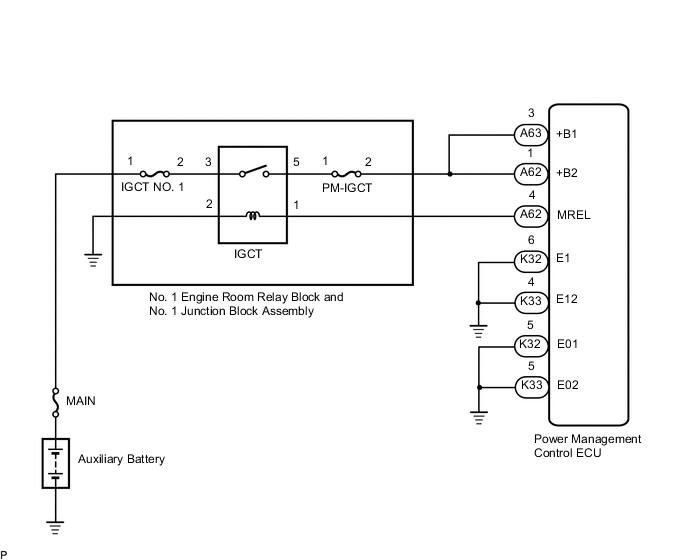
PROCEDURE
-
CHECK POWER MANAGEMENT CONTROL ECU (+B1, +B2 VOLTAGE)
-
Turn the power switch on (IG).
-
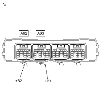
*a Component with harness connected
(Power Management Control ECU)
Measure the voltage according to the value(s) in the table below.
Standard Voltage Tester Connection Condition Specified Condition A63-3 (+B1) - Body ground Power switch on (IG) 11 to 14 V A62-1 (+B2) - Body ground Power switch on (IG) 11 to 14 V -
Turn the power switch off.
Result Proceed to OK NG
NG 
CHECK POWER MANAGEMENT CONTROL ECU (MREL VOLTAGE) Click here
OK 
-
-
CHECK HARNESS AND CONNECTOR (POWER MANAGEMENT CONTROL ECU - BODY GROUND)
-
Disconnect the K32 and K33 power management control ECU connectors.
-
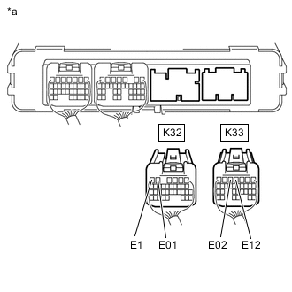
*a Rear view of wire harness connector
(to Power Management Control ECU)
Measure the resistance according to the value(s) in the table below.
Standard Resistance Tester Connection Condition Specified Condition K32-5 (E01) - Body ground Always Below 1 Ω K32-6 (E1) - Body ground Always Below 1 Ω K33-4 (E12) - Body ground Always Below 1 Ω K33-5 (E02) - Body ground Always Below 1 Ω -
Reconnect the K32 and K33 power management control ECU connectors.
Result Proceed to OK NG
OK 
GO TO PROBLEM SYMPTOMS TABLE Click here
NG
REPAIR OR REPLACE HARNESS OR CONNECTOR
-
-
CHECK POWER MANAGEMENT CONTROL ECU (MREL VOLTAGE)
-
Turn the power switch on (IG).
-
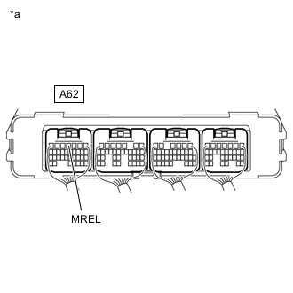
*a Component with harness connected
(Power Management Control ECU)
Measure the voltage according to the value(s) in the table below.
Standard Voltage Tester Connection Condition Specified Condition A62-4 (MREL) - Body ground Power switch on (IG) 11 to 14 V -
Turn the power switch off.
Result Proceed to OK NG
NG
REPLACE POWER MANAGEMENT CONTROL ECU Click here
OK
-
-
CHECK FUSE (PM-IGCT)
-
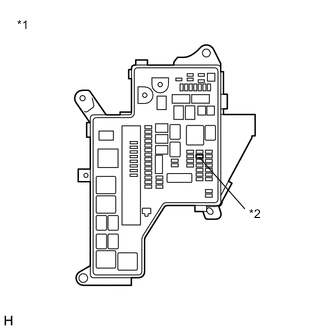
*1 No. 1 Engine Room Relay Block and No. 1 Junction Block Assembly *2 PM-IGCT Fuse Remove the PM-IGCT fuse from the No. 1 engine room relay block and No. 1 junction block assembly.
-
Measure the resistance according to the value(s) in the table below.
Standard Resistance Tester Connection Condition Specified Condition PM-IGCT fuse terminals Always Below 1 Ω -
*1 No. 1 Engine Room Relay Block and No. 1 Junction Block Assembly *2 PM-IGCT Fuse Install the PM-IGCT fuse.
Result Proceed to OK NG
NG
CHECK HARNESS AND CONNECTOR (NO. 1 ENGINE ROOM RELAY BLOCK AND NO. 1 JUNCTION BLOCK ASSEMBLY - POWER MANAGEMENT CONTROL ECU) Click here
OK
-
-
CHECK FUSE (IGCT NO. 1)
Result Proceed to OK NG
-
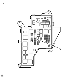
*1 No. 1 Engine Room Relay Block and No. 1 Junction Block Assembly *2 IGCT NO. 1 Fuse Remove the IGCT NO. 1 fuse from the No. 1 engine room relay block and No. 1 junction block assembly.
-
Measure the resistance according to the value(s) in the table below.
Standard Resistance Tester Connection Condition Specified Condition IGCT NO. 1 fuse terminals Always Below 1 Ω -
Install the IGCT NO. 1 fuse.
Result Proceed to OK NG
NG
CHECK HARNESS AND CONNECTOR (NO. 1 ENGINE ROOM RELAY BLOCK AND NO. 1 JUNCTION BLOCK ASSEMBLY) Click here
OK
-
-
INSPECT RELAY (IGCT)
-
Remove the IGCT relay from the No. 1 engine room relay block and No. 1 junction block assembly.
-
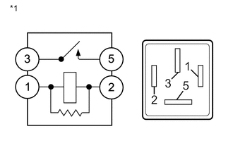
*1 IGCT Relay Measure the resistance according to the value(s) in the table below.
Standard Resistance Tester Connection Condition Specified Condition 3 - 5 Auxiliary battery voltage is not applied between terminals 1 and 2 10 kΩ or higher Auxiliary battery voltage is applied between terminals 1 and 2 Below 1 Ω -
Install the IGCT relay.
Result Proceed to OK NG
NG
REPLACE RELAY (IGCT)
OK
-
-
CHECK HARNESS AND CONNECTOR (NO. 1 ENGINE ROOM RELAY BLOCK AND NO. 1 JUNCTION BLOCK ASSEMBLY - POWER MANAGEMENT CONTROL ECU)
-
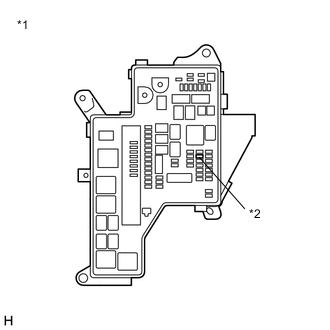
*1 No. 1 Engine Room Relay Block and No. 1 Junction Block Assembly *2 PM-IGCT Fuse Remove the PM-IGCT fuse from the No. 1 engine room relay block and No. 1 junction block assembly.
-
Disconnect the A62 and A63 power management control ECU connectors.
-
Measure the resistance according to the value(s) in the table below.
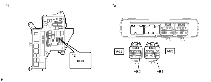
*1 No. 1 Engine Room Relay Block and No. 1 Junction Block Assembly *2 PM-IGCT Fuse *a Rear view of wire harness connector
(to Power Management Control ECU)
- - Standard Resistance Tester Connection Condition Specified Condition 2 (PM-IGCT fuse) - A63-3 (+B1) Always Below 1 Ω 2 (PM IGCT fuse) - A62-1 (+B2) Always Below 1 Ω -
Reconnect the A62 and A63 power management control ECU connectors.
-
Install the PM-IGCT fuse.
Result Proceed to OK NG
NG
REPAIR OR REPLACE HARNESS OR CONNECTOR
OK
-
-
CHECK HARNESS AND CONNECTOR (NO. 1 ENGINE ROOM RELAY BLOCK AND NO. 1 JUNCTION BLOCK ASSEMBLY)
-
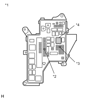
*1 No. 1 Engine Room Relay Block and No. 1 Junction Block Assembly *2 IGCT NO. 1 Fuse *3 PM-IGCT Fuse *4 IGCT Relay Remove the IGCT NO. 1 fuse, PM-IGCT fuse and IGCT relay from the No. 1 engine room relay block and No. 1 junction block assembly.
-
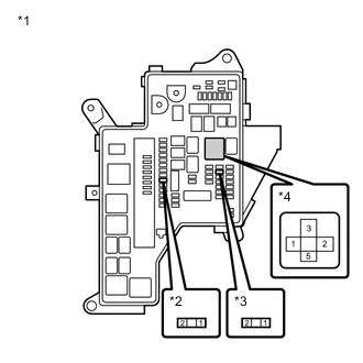
*1 No. 1 Engine Room Relay Block and No. 1 Junction Block Assembly *2 IGCT NO. 1 Fuse *3 PM IGCT Fuse *4 IGCT Relay Measure the resistance according to the value(s) in the table below.
Standard Resistance Tester Connection Condition Specified Condition 3 (IGCT relay) - 2 (IGCT NO. 1 fuse) Always Below 1 Ω 5 (IGCT relay) - 1 (PM-IGCT fuse) Always Below 1 Ω -
Install the IGCT NO. 1 fuse, PM-IGCT fuse and IGCT relay.
Result Proceed to OK NG
NG
REPAIR OR REPLACE HARNESS OR CONNECTOR
OK
-
-
CHECK HARNESS AND CONNECTOR (POWER MANAGEMENT CONTROL ECU - NO. 1 ENGINE ROOM RELAY BLOCK AND NO. 1 JUNCTION BLOCK ASSEMBLY)
-
Disconnect the A62 power management control ECU connector.
-
Remove the IGCT relay from the No. 1 engine room relay block and No. 1 junction block assembly.
-
Measure the resistance according to the value(s) in the table below.
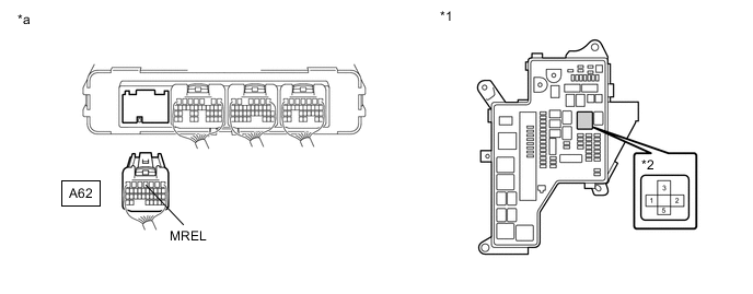
*1 No. 1 Engine Room Relay Block and No. 1 Junction Block Assembly *2 IGCT Relay *a Rear view of wire harness connector
(to Power Management Control ECU)
- - Standard Resistance Tester Connection Condition Specified Condition A62-4 (MREL) - 1 (IGCT relay) Always Below 1 Ω A62-4 (MREL) or 1 (IGCT relay) - Body ground and other terminals Always 10 kΩ or higher -
Install the IGCT relay.
-
Reconnect the A62 power management control ECU connector.
Result Proceed to OK NG
NG
REPAIR OR REPLACE HARNESS OR CONNECTOR
OK
-
-
CHECK HARNESS AND CONNECTOR (NO. 1 ENGINE ROOM RELAY BLOCK AND NO. 1 JUNCTION BLOCK ASSEMBLY - BODY GROUND)
-
Remove the IGCT relay from the No. 1 engine room relay block and No. 1 junction block assembly.
-
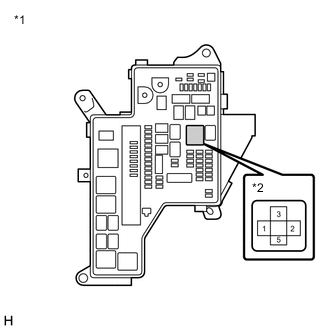
*1 No. 1 Engine Room Relay Block and No. 1 Junction Block Assembly *2 IGCT Relay Measure the resistance according to the value(s) in the table below.
Standard Resistance Tester Connection Condition Specified Condition 2 (IGCT relay) - Body ground Always Below 1 Ω -
Install the IGCT relay.
Result Proceed to OK NG
NG
REPAIR OR REPLACE HARNESS OR CONNECTOR
OK
-
-
CHECK HARNESS AND CONNECTOR (NO. 1 ENGINE ROOM RELAY BLOCK AND NO. 1 JUNCTION BLOCK ASSEMBLY)
-
Disconnect the inverter bus-bar plate sub-assembly from the AMD terminal (No. 1 engine room relay block and No. 1 junction block assembly side).
-
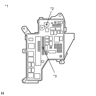
*1 No. 1 Engine Room Relay Block and No. 1 Junction Block Assembly *2 AMD Terminal *3 IGCT NO. 1 Fuse Remove the IGCT NO. 1 fuse and PM IGCT fuse from the No. 1 engine room relay block and No. 1 junction block assembly.
-
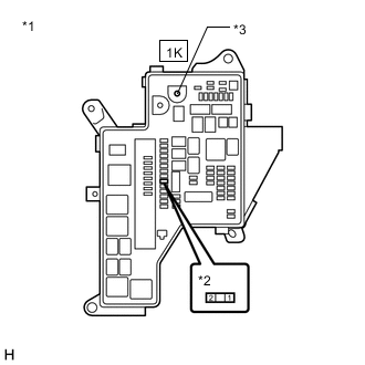
*1 No. 1 Engine Room Relay Block and No. 1 Junction Block Assembly *2 IGCT NO. 1 Fuse *3 AMD Terminal Measure the resistance according to the value(s) in the table below.
Standard Resistance Tester Connection Condition Specified Condition 1K-1 (AMD terminal) - 1 (IGCT No. 1 fuse) Always Below 1 Ω -
Install the IGCT No. 1 fuse.
-
Reconnect the inverter bus-bar plate sub-assembly from the AMD terminal (No. 1 engine room relay block and No. 1 junction block assembly side).
Result Proceed to OK NG
OK
CHECK FOR INTERMITTENT PROBLEMS Click here
NG
-
-
CHECK FUSE (DC/DC)
Result Proceed to OK NG
-
Check the DC/DC fuse in the No. 1 engine room relay block and No. 1 junction block assembly for improper installation.
OK The DC/DC fuse is installed securely. -
Remove the DC/DC fuse from the No. 1 engine room relay block and No. 1 junction block assembly.
-
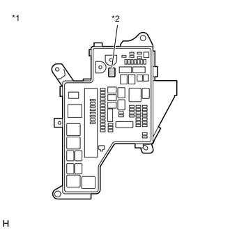
*1 No. 1 Engine Room Relay Block and No. 1 Junction Block Assembly *2 DC/DC Fuse Measure the resistance according to the value(s) in the table below.
Standard Resistance Tester Connection Condition Specified Condition DC/DC fuse terminals Always Below 1 Ω -
Install the DC/DC fuse.
Result Proceed to OK NG
OK
REPAIR OR REPLACE HARNESS OR CONNECTOR
NG
REPLACE FUSE (DC/DC)
-
-
CHECK HARNESS AND CONNECTOR (NO. 1 ENGINE ROOM RELAY BLOCK AND NO. 1 JUNCTION BLOCK ASSEMBLY)
-
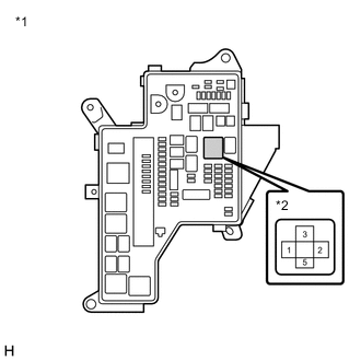
*1 No. 1 Engine Room Relay Block and No. 1 Junction Block Assembly *2 IGCT Relay Remove the IGCT NO. 1 fuse, PM-IGCT fuse and IGCT relay from the No. 1 engine room relay block and No. 1 junction block assembly.
-
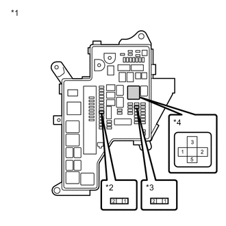
*1 No. 1 Engine Room Relay Block and No. 1 Junction Block Assembly *2 IGCT NO. 1 Fuse *3 PM-IGCT Fuse *4 IGCT Relay Measure the resistance according to the value(s) in the table below.
Standard Resistance Tester Connection Condition Specified Condition 3 (IGCT relay) or 2 (IGCT NO. 1 fuse) - Body ground and other terminals Always 10 kΩ or higher 5 (IGCT relay) or 2 (PM-IGCT fuse) - Body ground and other terminals Always 10 kΩ or higher -
Install the IGCT NO. 1 fuse, PM-IGCT fuse and IGCT relay.
Result Proceed to OK NG
OK
REPLACE FUSE (IGCT NO. 1)
NG
-
-
REPAIR OR REPLACE HARNESS OR CONNECTOR
Result Proceed to NEXT
NEXT
REPLACE FUSE (IGCT NO. 1)
-
CHECK HARNESS AND CONNECTOR (NO. 1 ENGINE ROOM RELAY BLOCK AND NO. 1 JUNCTION BLOCK ASSEMBLY - POWER MANAGEMENT CONTROL ECU)
-
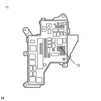
*1 No. 1 Engine Room Relay Block and No. 1 Junction Block Assembly *2 PM-IGCT Fuse Remove the PM-IGCT fuse from the No. 1 engine room relay block and No. 1 junction block assembly.
-
Disconnect the A62 and A63 power management control ECU connectors.
-
Measure the resistance according to the value(s) in the table below.
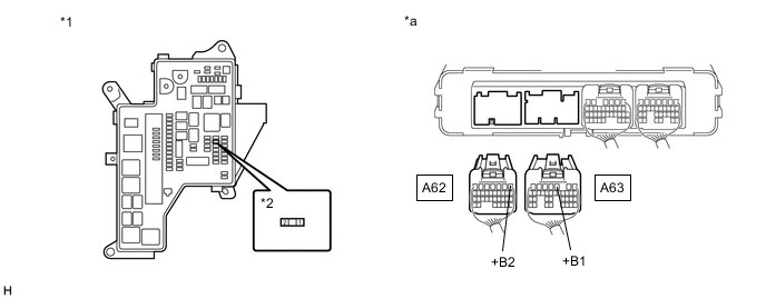
*1 No. 1 Engine Room Relay Block and No. 1 Junction Block Assembly *2 PM-IGCT Fuse *a Rear view of wire harness connector
(to Power Management Control ECU)
- - Standard Resistance Tester Connection Condition Specified Condition 2 (PM-IGCT fuse) or A63-3 (+B1) - Body ground and other terminals Always 10 kΩ or higher 2 (PM-IGCT fuse) or A62-1 (+B2) - Body ground and other terminals Always 10 kΩ or higher -
Reconnect the A62 and A63 power management control ECU connectors.
-
Install the PM-IGCT fuse.
Result Proceed to OK NG
OK
REPLACE FUSE (PM-IGCT)
NG
-
-
REPAIR OR REPLACE HARNESS OR CONNECTOR
Result Proceed to NEXT
NEXT
REPLACE FUSE (PM-IGCT)