HYBRID CONTROL SYSTEM Indicator Circuit
DESCRIPTION
In accordance with the shift lever position, each shift position indicator light will turn on.
WIRING DIAGRAM
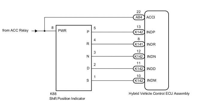
PROCEDURE
-
CHECK SHIFT POSITION INDICATOR
-
Turn the power switch on (ACC).
-
Check that each shift position indicator light turns on correctly.
Result Result Proceed to All shift position indicator lights turn on simultaneously A Shift position indicator lights other than corresponding one turn on A Corresponding shift position indicator light does not turn on B No shift position indicator lights turn on B -
Turn the power switch off.
B 
CHECK HARNESS AND CONNECTOR (SHIFT POSITION SENSOR POWER SOURCE CIRCUIT) Click here
A 
-
-
CHECK HARNESS AND CONNECTOR (CHECK FOR SHORT TO GND)
-
Disconnect the K141 and K142 hybrid vehicle control ECU assembly connectors.
-
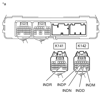
*a Rear view of wire harness connector
(to Hybrid Vehicle Control ECU Assembly)
Measure the resistance according to the value(s) in the table below.
Standard Resistance Tester Connection Condition Specified Condition K142-13 (INDP) - Body ground and other terminals Power switch off 10 kΩ or higher K141-8 (INDR) - Body ground and other terminals Power switch off 10 kΩ or higher K142-12 (INDN) - Body ground and other terminals Power switch off 10 kΩ or higher K142-11 (INDD) - Body ground and other terminals Power switch off 10 kΩ or higher K142-10 (INDM) - Body ground and other terminals Power switch off 10 kΩ or higher -
Reconnect the K141 and K142 hybrid vehicle control ECU assembly connectors.
Result Proceed to OK NG
OK 
REPLACE HYBRID VEHICLE CONTROL ECU ASSEMBLY Click here
NG
-
-
CHECK HARNESS AND CONNECTOR (HYBRID VEHICLE CONTROL ECU ASSEMBLY - SHIFT POSITION INDICATOR)
-
Disconnect the K141 and K142 hybrid vehicle control ECU assembly connectors.
-
Disconnect the K88 shift position indicator connector.
-
*a Rear view of wire harness connector
(to Hybrid Vehicle Control ECU Assembly)
Measure the resistance according to the value(s) in the table below.
Standard Resistance Tester Connection Condition Specified Condition K142-13 (INDP) - Body ground and other terminals Power switch off 10 kΩ or higher K141-8 (INDR) - Body ground and other terminals Power switch off 10 kΩ or higher K142-12 (INDN) - Body ground and other terminals Power switch off 10 kΩ or higher K142-11 (INDD) - Body ground and other terminals Power switch off 10 kΩ or higher K142-10 (INDM) - Body ground and other terminals Power switch off 10 kΩ or higher -
Reconnect the K88 shift position indicator connector.
-
Reconnect the K141 and K142 hybrid vehicle control ECU assembly connectors.
Result Proceed to OK NG
OK
REPLACE SHIFT POSITION INDICATOR Click here
NG
REPAIR OR REPLACE HARNESS OR CONNECTOR
-
-
CHECK HARNESS AND CONNECTOR (SHIFT POSITION SENSOR POWER SOURCE CIRCUIT)
-
Disconnect the K88 shift position indicator connector.
-
Turn the power switch on (ACC).
-
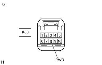
*a Front view of wire harness connector
(to Shift Position Indicator)
Measure the voltage according to the value(s) in the table below.
Standard Voltage Tester Connection Condition Specified Condition K88-8 (PWR) - Body ground Power switch on (ACC) 11 to 14 V -
Turn the power switch off.
-
Reconnect the K88 shift position indicator connector.
Result Proceed to OK NG
NG
REPAIR OR REPLACE POWER SOURCE CIRCUIT
OK
-
-
CHECK HARNESS AND CONNECTOR (POWER SOURCE TERMINAL ACCI)
-
Turn the power switch on (ACC).
-
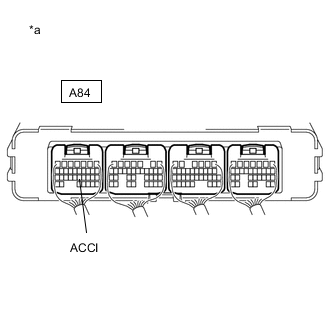
*a Component with harness connected
(Hybrid Vehicle Control ECU Assembly)
Measure the voltage according to the value(s) in the table below.
Standard Voltage Tester Connection Condition Specified Condition A84-22 (ACCI) - Body ground Power switch on (ACC) 11 to 14 V -
Turn the power switch off.
Result Proceed to OK NG
NG
REPAIR OR REPLACE POWER SOURCE CIRCUIT
OK
-
-
CHECK HARNESS AND CONNECTOR (CHECK FOR OPEN)
-
Disconnect the K141 and K142 hybrid vehicle control ECU assembly connectors.
-
Turn the power switch on (ACC).
-
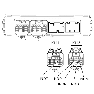
*a Rear view of wire harness connector
(to Hybrid Vehicle Control ECU Assembly)
Measure the voltage according to the value(s) in the table below.
Standard Voltage Tester Connection Condition Specified Condition K142-13 (INDP) - Body ground Power switch on (ACC) 11 to 14 V K141-8 (INDR) - Body ground Power switch on (ACC) 11 to 14 V K142-12 (INDN) - Body ground Power switch on (ACC) 11 to 14 V K142-11 (INDD) - Body ground Power switch on (ACC) 11 to 14 V K142-10 (INDM) - Body ground Power switch on (ACC) 11 to 14 V -
Turn the power switch off.
-
Reconnect the K141 and K142 hybrid vehicle control ECU Assembly connectors.
Result Proceed to OK NG
OK
REPLACE HYBRID VEHICLE CONTROL ECU ASSEMBLY Click here
NG
-
-
CHECK HARNESS AND CONNECTOR (HYBRID VEHICLE CONTROL ECU ASSEMBLY - SHIFT POSITION INDICATOR)
-
Disconnect the K141 and K142 hybrid vehicle control ECU assembly connectors.
-
Disconnect the K88 shift position indicator connector.
-
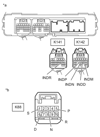
*a Rear view of wire harness connector
(to Hybrid Vehicle Control ECU Assembly)
*b Front view of wire harness connector
(to Shift Position Indicator)
Measure the resistance according to the value(s) in the table below.
Standard Resistance Tester Connection Condition Specified Condition K142-13 (INDP) - K88-5 (P) Always Below 1 Ω K141-8 (INDR) - K88-4 (R) Always Below 1 Ω K142-12 (INDN) - K88-3 (N) Always Below 1 Ω K142-11 (INDD) - K88-2 (D) Always Below 1 Ω K142-10 (INDM) - K88-1 (S) Always Below 1 Ω -
Reconnect the K88 shift position indicator connector.
-
Reconnect the K141 and K142 hybrid vehicle control ECU assembly connectors.
Result Proceed to OK NG
OK
REPLACE SHIFT POSITION INDICATOR Click here
NG
REPAIR OR REPLACE HARNESS OR CONNECTOR
-