| DTC Code | DTC Name |
|---|---|
| P0A40-504 | Drive Motor "A" Position Sensor Circuit Range / Performance |
DESCRIPTION
For a description of the inverter.
If an overvoltage occurs in the motor inverter or generator inverter, the MG ECU detects it and transmits this information to the hybrid vehicle control ECU assembly.
The term "drive motor A" indicates motor (MG2).
| DTC No. | Detection Item | DTC Detection Condition | Trouble Area | MIL | Warning Indicate |
|---|---|---|---|---|---|
| P0A40-504 | Drive Motor "A" Position Sensor Circuit Range / Performance | Motor inverter overvoltage signal detection (overvoltage due to hybrid vehicle transmission assembly malfunction) Overvoltage is detected after boosting.* (1 trip detection logic) |
|
Comes on | Master Warning Light: Comes on |
*: The hybrid vehicle transmission assembly is suspected to be the main cause of the malfunction.
| DTC No. | Data List |
|---|---|
| P0A40-504 | VH-Voltage after Boosting |
CAUTION / NOTICE / HINT
-
Before inspecting the high-voltage system or disconnecting the low voltage connector of the inverter with converter assembly, take safety precautions such as wearing insulated gloves and removing the service plug grip to prevent electrical shocks. After removing the service plug grip, put it in your pocket to prevent other technicians from accidentally reconnecting it while you are working on the high-voltage system.
-
After removing the service plug grip, wait for at least 10 minutes before touching any of the high-voltage connectors or terminals. After waiting for 10 minutes, check the voltage at the terminals in the inspection point in the inverter with converter assembly. The voltage should be 0 V before beginning work.
Tip:Waiting for at least 10 minutes is required to discharge the high-voltage capacitor inside the inverter with converter assembly.
After turning the power switch off, waiting time may be required before disconnecting the cable from the negative (-) auxiliary battery terminal. Therefore, make sure to read the disconnecting the cable from the negative (-) auxiliary battery terminal notices before proceeding with work.
After the repair, clear the DTCs and perform the following procedure to check that DTCs are not output.
-
With the vehicle engine stopped, the power switch on (READY) and the shift lever in P, depress the accelerator pedal to start the engine.
PROCEDURE
- Click here
CHECK DTC OUTPUT (HYBRID CONTROL)
-
Connect the GTS to the DLC3.
-
Turn the power switch on (IG).
-
Enter the following menus: Powertrain / Hybrid Control / Trouble Codes.
-
Check for DTCs.
- Powertrain > Hybrid Control > Trouble Codes
-
-
Result Result Proceed to P0A40-504 only is output, or DTCs except the ones in the table below are also output. A Any of the following DTCs including pending DTCs are also output. B Relevant DTC P06B0-163 Sensor Power Supply "A" Circuit / Open P06D6-511 Sensor Reference Voltage "F" Circuit / Open P06E6-164 Sensor Power Supply "C" Circuit / Open P0A1A-151, 166, 517, 658, 791, 809 Generator Control Module P0A1B-198, 505, 554, 786, 794, 806 Drive Motor "A" Control Module P0A1D (all INF codes)*1 Hybrid Powertrain Control Module P0A3F-243 Drive Motor "A" Position Sensor Circuit P0A40-500, 506, 556, 808 Drive Motor "A" Position Sensor Circuit Range / Performance P0A41-245 Drive Motor "A" Position Sensor Circuit Low P0A4B-253 Generator Position Sensor Circuit P0A4C-513, 518, 811 Generator Position Sensor Circuit Range / Performance P0A4D-255 Generator Position Sensor Circuit Low P0A78-287, 555, 807 Drive Motor "A" Inverter Performance P0A7A-325, 810 Generator Inverter Performance P0A93-346 Inverter Cooling System Performance P0ADB-227 Hybrid Battery Positive Contactor Control Circuit Low P0ADC-226 Hybrid Battery Positive Contactor Control Circuit High P0ADF-229 Hybrid Battery Negative Contactor Control Circuit Low P0AE0-228 Hybrid Battery Negative Contactor Control Circuit High P0BEA-290 Drive Motor "A" Phase V Current Sensor Circuit Range / Performance P0BEE-298 Drive Motor "A" Phase W Current Sensor Circuit Range / Performance P0C73-776 Motor Electronics Coolant Pump "A" Control Performance P0C76-523 Hybrid Battery System Discharge Time Too Long P0D2E-565, 586 Drive Motor "A" Inverter Voltage Sensor Circuit Range / Performance P0D2F-266 Drive Motor "A" Inverter Voltage Sensor Circuit Low P0D30-267 Drive Motor "A" Inverter Voltage Sensor Circuit High P0E05-328 Generator Phase V Current Sensor Circuit Range / Performance P0E09-336 Generator Phase W Current Sensor Circuit Range / Performance P0E32-585 DC/DC Converter Voltage Sensor "A" Range / Performance P0E33-589 DC/DC Converter Voltage Sensor "A" Low P0E34-590 DC/DC Converter Voltage Sensor "A" High P1C2A-155 Generator A/D Converter Circuit P1C2B-192 Drive Motor "A" A/D Converter Circuit P1C2D-587 Hybrid Battery Voltage / DC/DC Converter Voltage Correlation P1C3C-294 Drive Motor "A" Phase V Current Sensor Correlation P1C3D-302 Drive Motor "A" Phase W Current Sensor Correlation P1C3E-333 Generator Phase V Current Sensor Correlation P1C3F-341 Generator Phase W Current Sensor Correlation P1C4A-288 Drive Motor "A" Phase V Current Sensor Sub Circuit Range / Performance P1C4F-296 Drive Motor "A" Phase W Current Sensor Sub Circuit Range / Performance P1C54-326 Generator Phase V Current Sensor Sub Circuit Range / Performance P1C59-334 Generator Phase W Current Sensor Sub Circuit Range / Performance P1C6D-501 Drive Motor "A" Phase V Current Sensor Offset Range / Performance P1C6E-502 Drive Motor "A" Phase W Current Sensor Offset Range / Performance P1C71-515 Generator Phase V Current Sensor Offset Range / Performance P1C72-516 Generator Phase W Current Sensor Offset Range / Performance P1C73-512 Sensor Standard Voltage "F" Circuit / Open P1CA6-156 Generator Control Module Malfunction P1CA7-193 Drive Motor Control Module Malfunction P1CAC-200 Generator Position Sensor Angle Malfunction P1CAD-168 Drive Motor "A" Position Sensor Angle Malfunction P1CAF-792 Generator Position Sensor REF Signal Cycle Malfunction P1CB0-795 Drive Motor "A" Position Sensor REF Signal Cycle Malfunction P1CB2-793 Generator Position Sensor REF Signal Stop Malfunction P1CB3-796 Drive Motor "A" Position Sensor REF Signal Stop Malfunction P3004-803 High Voltage Power Resource P3133-659 Communication Error from Generator to Drive Motor "A" P3134-661 Communication Error from Drive Motor "A" to Generator P314A-828 Inverter Coolant Pump Speed Signal Tip:
-
*1: If any INF codes are output for this DTC, refer to the corresponding diagnostic procedure.
-
P0A40-504 may be stored due to a malfunction which also causes DTCs in the preceding table to be stored. In this case, first troubleshoot the output DTCs in the preceding table. Then, perform a test to attempt to reproduce the problems, and check that no DTCs are output.
-
Turn the power switch off.
- AClick here
- B
GO TO DTC CHART (HYBRID CONTROL SYSTEM)Click here
-
- Click here
CHECK CONNECTOR CONNECTION CONDITION (INVERTER WITH CONVERTER ASSEMBLY CONNECTOR)
Result Result Proceed to OK A NG (The connector is not connected securely.) B NG (The terminals are not making secure contact or are deformed, or water or foreign matter exists in the connector.) C CAUTION:Be sure to wear insulated gloves.
-
Check that the service plug grip is not installed.
Note:After removing the service plug grip, do not turn the power switch on (READY), unless instructed by the repair manual because this may cause a malfunction.
-
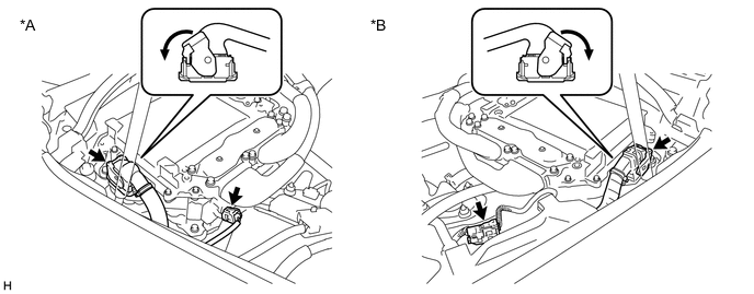
*A for LHD *B for RHD Check the connection condition of the low voltage connector of the inverter with converter assembly and the contact pressure of each terminal. Check the terminals for deformation, and check the connector for water ingress and foreign matter.
Note:Before disconnecting the connector, confirm that it is properly connected by checking that the locking claws are engaged and that the connector does not pull out.
OK - The connector is connected securely. - The terminals are not deformed and are connected securely. - No water or foreign matter in the connector. Result Result Proceed to OK A NG (The connector is not connected securely.) B NG (The terminals are not making secure contact or are deformed, or water or foreign matter exists in the connector.) C Tip:When connecting the connector, insert it with the locking lever in the raised position. Rotate the lever downward and make sure that the connector is pulled into its socket. When the locking lever is in its fully closed position, a click will be heard as its locking claws engage. After the click is heard, pull up on the connector to confirm that it is properly connected.
- AClick here
- B
CONNECT SECURELY
- C
REPAIR OR REPLACE HARNESS OR CONNECTOR
-
- Click here
CHECK HARNESS AND CONNECTOR (INVERTER WITH CONVERTER ASSEMBLY - GENERATOR RESOLVER)
Result Proceed to OK NG CAUTION:Be sure to wear insulated gloves.
-
Check that the service plug grip is not installed.
Note:After removing the service plug grip, do not turn the power switch on (READY), unless instructed by the repair manual because this may cause a malfunction.
-
Disconnect the A28*1 orA29*2 inverter with converter assembly connector.
-
*1: for LHD
-
*2: for RHD
-
-
Connect the cable to the negative (-) auxiliary battery terminal.
-
Turn the power switch on (IG).
-

*A for LHD *B for RHD *a Front view of wire harness connector
(to Inverter with Converter Assembly)
Measure the voltage according to the value(s) in the table below.
Standard Voltage Table 2. for LHD Tester Connection Condition Specified Condition A28-20 (GRF) - Body ground Power switch on (IG) Below 1 V A28-9 (GRFG) - Body ground Power switch on (IG) Below 1 V A28-18 (GSN) - Body ground Power switch on (IG) Below 1 V A28-7 (GSNG) - Body ground Power switch on (IG) Below 1 V A28-17 (GCS) - Body ground Power switch on (IG) Below 1 V A28-6 (GCSG) - Body ground Power switch on (IG) Below 1 V Table 3. for RHD Tester Connection Condition Specified Condition A29-20 (GRF) - Body ground Power switch on (IG) Below 1 V A29-9 (GRFG) - Body ground Power switch on (IG) Below 1 V A29-18 (GSN) - Body ground Power switch on (IG) Below 1 V A29-7 (GSNG) - Body ground Power switch on (IG) Below 1 V A29-17 (GCS) - Body ground Power switch on (IG) Below 1 V A29-6 (GCSG) - Body ground Power switch on (IG) Below 1 V Note:Turning the power switch on (IG) with the inverter with converter assembly disconnected causes other DTCs to be stored. Clear the DTCs after performing this inspection.
-
Turn the power switch off.
-
Disconnect the cable from the negative (-) auxiliary battery terminal.
-
Reconnect the A28*1 or A29*2 inverter with converter assembly connector.
-
*1: for LHD
-
*2: for RHD
Result Proceed to OK NG -
- OKClick here
- NG
REPAIR OR REPLACE HARNESS OR CONNECTOR
-
- Click here
CHECK GENERATOR RESOLVER
Result Proceed to OK NG CAUTION:Be sure to wear insulated gloves.
-
Check that the service plug grip is not installed.
Note:After removing the service plug grip, do not turn the power switch on (READY), unless instructed by the repair manual because this may cause a malfunction.
-
Disconnect the A28*1 orA29*2 inverter with converter assembly connector.
-
*1: for LHD
-
*2: for RHD
-
-
*A for LHD *B for RHD *a Front view of wire harness connector
(to Inverter with Converter Assembly)
Measure the resistance according to the value(s) in the table below.
Standard Resistance Table 4. for LHD Tester Connection Condition Specified Condition A28-20 (GRF) - A28-9 (GRFG) Power switch off 4.2 to 12.5 Ω A28-18 (GSN) - A28-7 (GSNG) Power switch off 9.8 to 20.1 Ω A28-17 (GCS) - A28-6 (GCSG) Power switch off 9.8 to 20.1 Ω Table 5. for RHD Tester Connection Condition Specified Condition A29-20 (GRF) - A29-9 (GRFG) Power switch off 4.2 to 12.5 Ω A29-18 (GSN) - A29-7 (GSNG) Power switch off 9.8 to 20.1 Ω A29-17 (GCS) - A29-6 (GCSG) Power switch off 9.8 to 20.1 Ω Tip:To correct the variation of the measured resistance due to temperature, use the following formula to calculate the resistance at 20°C (68°F).
R20 = Rt / {1 + 0.00393 X (T - 20)}
The calculation is based on the following:
R20: Resistance at 20°C (68°F) (mΩ)
Rt: Measured resistance (mΩ)
T: Temperature when the resistance is measured (°C (°F).)
Standard Resistance (Check for Short) Table 6. for LHD Tester Connection Condition Specified Condition A28-20 (GRF) or A28-9 (GRFG) - Body ground and other terminals Power switch off 1 MΩ or higher A28-18 (GSN) or A28-7 (GSNG) - Body ground and other terminals Power switch off 1 MΩ or higher A28-17 (GCS) or A28-6 (GCSG) - Body ground and other terminals Power switch off 1 MΩ or higher Table 7. for RHD Tester Connection Condition Specified Condition A29-20 (GRF) or A29-9 (GRFG) - Body ground and other terminals Power switch off 1 MΩ or higher A29-18 (GSN) or A29-7 (GSNG) - Body ground and other terminals Power switch off 1 MΩ or higher A29-17 (GCS) or A29-6 (GCSG) - Body ground and other terminals Power switch off 1 MΩ or higher -
Reconnect the A28*1 or A29*2 inverter with converter assembly connector.
-
*1: for LHD
-
*2: for RHD
Result Proceed to OK NG -
- OKClick here
- NGClick here
-
- Click here
CHECK HARNESS AND CONNECTOR (INVERTER WITH CONVERTER ASSEMBLY - MOTOR RESOLVER)
Result Proceed to OK NG CAUTION:Be sure to wear insulated gloves.
-
Check that the service plug grip is not installed.
Note:After removing the service plug grip, do not turn the power switch on (READY), unless instructed by the repair manual because this may cause a malfunction.
-
Disconnect the A28*1 orA29*2 inverter with converter assembly connector.
-
*1: for LHD
-
*2: for RHD
-
-
Connect the cable to the negative (-) auxiliary battery terminal.
-
Turn the power switch on (IG).
-
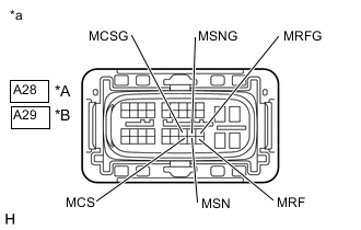
*A for LHD *B for RHD *a Front view of wire harness connector
(to Inverter with Converter Assembly)
Measure the voltage according to the value(s) in the table below.
Standard Voltage Table 8. for LHD Tester Connection Condition Specified Condition A28-40 (MRF) - Body ground Power switch on (IG) Below 1 V A28-29 (MRFG) - Body ground Power switch on (IG) Below 1 V A28-39 (MSN) - Body ground Power switch on (IG) Below 1 V A28-28 (MSNG) - Body ground Power switch on (IG) Below 1 V A28-38 (MCS) - Body ground Power switch on (IG) Below 1 V A28-27 (MCSG) - Body ground Power switch on (IG) Below 1 V Table 9. for RHD Tester Connection Condition Specified Condition A29-40 (MRF) - Body ground Power switch on (IG) Below 1 V A29-29 (MRFG) - Body ground Power switch on (IG) Below 1 V A29-39 (MSN) - Body ground Power switch on (IG) Below 1 V A29-28 (MSNG) - Body ground Power switch on (IG) Below 1 V A29-38 (MCS) - Body ground Power switch on (IG) Below 1 V A29-27 (MCSG) - Body ground Power switch on (IG) Below 1 V Note:Turning the power switch on (IG) with the inverter with converter assembly disconnected causes other DTCs to be stored. Clear the DTCs after performing this inspection.
-
Turn the power switch off.
-
Disconnect the cable from the negative (-) auxiliary battery terminal.
-
Reconnect the A28*1 or A29*2 inverter with converter assembly connector.
-
*1: for LHD
-
*2: for RHD
Result Proceed to OK NG -
- OKClick here
- NG
REPAIR OR REPLACE HARNESS OR CONNECTOR
-
- Click here
CHECK MOTOR RESOLVER
Result Proceed to OK NG CAUTION:Be sure to wear insulated gloves.
-
Check that the service plug grip is not installed.
Note:After removing the service plug grip, do not turn the power switch on (READY), unless instructed by the repair manual because this may cause a malfunction.
-
Disconnect the A28*1 orA29*2 inverter with converter assembly connector.
-
*1: for LHD
-
*2: for RHD
-
-
*A for LHD *B for RHD *a Front view of wire harness connector
(to Inverter with Converter Assembly)
Measure the resistance according to the value(s) in the table below.
Standard Resistance Table 10. for LHD Tester Connection Condition Specified Condition A28-40 (MRF) - A28-29 (MRFG) Power switch off 4.2 to 12.5 Ω A28-39 (MSN) - A28-28 (MSNG) Power switch off 9.8 to 24.8 Ω A28-38 (MCS) - A28-27 (MCSG) Power switch off 9.8 to 24.8 Ω Table 11. for RHD Tester Connection Condition Specified Condition A29-40 (MRF) - A29-29 (MRFG) Power switch off 4.2 to 12.5 Ω A29-39 (MSN) - A29-28 (MSNG) Power switch off 9.8 to 24.8 Ω A29-38 (MCS) - A29-27 (MCSG) Power switch off 9.8 to 24.8 Ω Tip:To correct the variation of the measured resistance due to temperature, use the following formula to calculate the resistance at 20°C (68°F).
R20 = Rt / {1 + 0.00393 X (T - 20)}
The calculation is based on the following:
R20: Resistance at 20°C (68°F) (mΩ)
Rt: Measured resistance (mΩ)
T: Temperature when the resistance is measured (°C (°F).)
Standard Resistance (Check for Short) Table 12. for LHD Tester Connection Condition Specified Condition A28-40 (MRF) or A28-29 (MRFG) - Body ground and other terminals Power switch off 1 MΩ or higher A28-39 (MSN) or A28-28 (MSNG) - Body ground and other terminals Power switch off 1 MΩ or higher A28-38 (MCS) or A28-27 (MCSG) - Body ground and other terminals Power switch off 1 MΩ or higher Table 13. for RHD Tester Connection Condition Specified Condition A29-40 (MRF) or A29-29 (MRFG) - Body ground and other terminals Power switch off 1 MΩ or higher A29-39 (MSN) or A29-28 (MSNG) - Body ground and other terminals Power switch off 1 MΩ or higher A29-38 (MCS) or A29-27 (MCSG) - Body ground and other terminals Power switch off 1 MΩ or higher -
Reconnect the A28*1 or A29*2 inverter with converter assembly connector.
-
*1: for LHD
-
*2: for RHD
Result Proceed to OK NG -
- OKClick here
- NGClick here
-
- Click here
CHECK CONNECTOR CONNECTION CONDITION (GENERATOR RESOLVER CONNECTOR)
Result Result Proceed to OK A NG (The connector is not connected securely.) B NG (The terminals are not making secure contact or are deformed, or water or foreign matter exists in the connector.) C
-
Remove the hybrid vehicle transmission assembly.
-
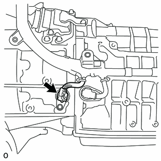
Check the connection condition of the generator resolver connector and the contact pressure of each terminal. Check the terminals for deformation, and check the connector for water ingress and foreign matter.
OK - The connector is connected securely. - The terminals are not deformed and are connected securely. - No water or foreign matter in the connector. Result Result Proceed to OK A NG (The connector is not connected securely.) B NG (The terminals are not making secure contact or are deformed, or water or foreign matter exists in the connector.) C
- AClick here
- B
CONNECT SECURELY
- C
REPAIR OR REPLACE HARNESS OR CONNECTOR
-
- Click here
CHECK CONNECTOR CONNECTION CONDITION (MOTOR RESOLVER CONNECTOR)
Result Result Proceed to OK A NG (The connector is not connected securely.) B NG (The terminals are not making secure contact or are deformed, or water or foreign matter exists in the connector.) C
-
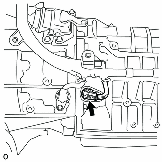
Check the connection condition of the motor resolver connector and the contact pressure of each terminal. Check the terminals for deformation, and check the connector for water ingress and foreign matter.
OK - The connector is connected securely. - The terminals are not deformed and are connected securely. - No water or foreign matter in the connector. Result Result Proceed to OK A NG (The connector is not connected securely.) B NG (The terminals are not making secure contact or are deformed, or water or foreign matter exists in the connector.) C -
Install the hybrid vehicle transmission assembly.
- A
REPLACE INVERTER WITH CONVERTER ASSEMBLYClick here
- B
CONNECT SECURELY
- C
REPAIR OR REPLACE HARNESS OR CONNECTOR
-
- Click here
CHECK CONNECTOR CONNECTION CONDITION (MOTOR RESOLVER CONNECTOR)
Result Result Proceed to OK A NG (The connector is not connected securely.) B NG (The terminals are not making secure contact or are deformed, or water or foreign matter exists in the connector.) C
-
Remove the hybrid vehicle transmission assembly.
-
Check the connection condition of the motor resolver connector and the contact pressure of each terminal. Check the terminals for deformation, and check the connector for water ingress and foreign matter.
OK - The connector is connected securely. - The terminals are not deformed and are connected securely. - No water or foreign matter in the connector. Result Result Proceed to OK A NG (The connector is not connected securely.) B NG (The terminals are not making secure contact or are deformed, or water or foreign matter exists in the connector.) C
- AClick here
- B
CONNECT SECURELY
- C
REPAIR OR REPLACE HARNESS OR CONNECTOR
-
- Click here
INSPECT HYBRID VEHICLE TRANSMISSION ASSEMBLY (MOTOR RESOLVER)
Result Proceed to OK NG
-
Disconnect the F51 motor resolver connector.
-
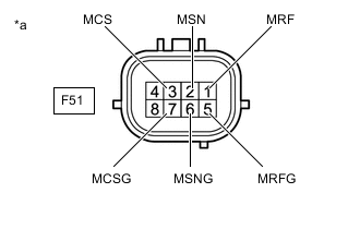
*a Component without harness connected
(Motor Resolver (Hybrid Vehicle Transmission Assembly))
Measure the resistance according to the value(s) in the table below.
Standard Resistance Tester Connection Condition Specified Condition F51-1 (MRF) - F51-5 (MRFG) Power switch off 6.0 to 12.0 Ω F51-2 (MSN) - F51-6 (MSNG) Power switch off 12.5 to 24.5 Ω F51-3 (MCS) - F51-7 (MCSG) Power switch off 12.5 to 24.5 Ω Tip:To correct the variation of the measured resistance due to temperature, use the following formula to calculate the resistance at 20°C (68°F).
R20 = Rt / {1 + 0.00393 X (T - 20)}
The calculation is based on the following:
R20: Resistance at 20°C (68°F) (mΩ)
Rt: Measured resistance (mΩ)
T: Temperature when the resistance is measured (°C (°F).)
Standard Resistance (Check for Short) Tester Connection Condition Specified Condition F51-1 (MRF) - Body ground and other terminals (except 5 (MRFG)) Power switch off 1 MΩ or higher F51-5 (MRFG) - Body ground and other terminals (except 1 (MRF)) Power switch off 1 MΩ or higher F51-2 (MSN) - Body ground and other terminals (except 6 (MSNG)) Power switch off 1 MΩ or higher F51-6 (MSNG) - Body ground and other terminals (except 2 (MSN)) Power switch off 1 MΩ or higher F51-3 (MCS) - Body ground and other terminals (except 7 (MCSG)) Power switch off 1 MΩ or higher F51-7 (MCSG) - Body ground and other terminals (except 3 (MCS)) Power switch off 1 MΩ or higher Tip:The motor resolver is not available as a supply part. If it requires replacement, replace the hybrid vehicle transmission assembly.
-
Reconnect the F51 motor resolver connector.
Result Proceed to OK NG
- OK
REPAIR OR REPLACE HARNESS OR CONNECTOR
- NG
REPLACE HYBRID VEHICLE TRANSMISSION ASSEMBLYClick here
-
- Click here
CHECK CONNECTOR CONNECTION CONDITION (GENERATOR RESOLVER CONNECTOR)
Result Result Proceed to OK A NG (The connector is not connected securely.) B NG (The terminals are not making secure contact or are deformed, or water or foreign matter exists in the connector.) C
-
Remove the hybrid vehicle transmission assembly.
-
Check the connection condition of the generator resolver connector and the contact pressure of each terminal. Check the terminals for deformation, and check the connector for water ingress and foreign matter.
OK - The connector is connected securely. - The terminals are not deformed and are connected securely. - No water or foreign matter in the connector. Result Result Proceed to OK A NG (The connector is not connected securely.) B NG (The terminals are not making secure contact or are deformed, or water or foreign matter exists in the connector.) C
- AClick here
- B
CONNECT SECURELY
- C
REPAIR OR REPLACE HARNESS OR CONNECTOR
-
- Click here
INSPECT HYBRID VEHICLE TRANSMISSION ASSEMBLY (GENERATOR RESOLVER)
Result Proceed to OK NG
-
Disconnect the F50 generator resolver connector.
-
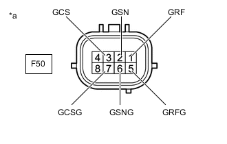
*a Component without harness connected
(Generator Resolver (Hybrid Vehicle Transmission Assembly))
Measure the resistance according to the value(s) in the table below.
Standard Resistance Tester Connection Condition Specified Condition F50-1 (GRF) - F50-5 (GRFG) Power switch off 5.8 to 11.8 Ω F50-2 (GSN) - F50-6 (GSNG) Power switch off 11.7 to 17.7 Ω F50-3 (GCS) - F50-7 (GCSG) Power switch off 11.7 to 17.7 Ω Tip:To correct the variation of the measured resistance due to temperature, use the following formula to calculate the resistance at 20°C (68°F).
R20 = Rt / {1 + 0.00393 X (T - 20)}
The calculation is based on the following:
R20: Resistance at 20°C (68°F) (mΩ)
Rt: Measured resistance (mΩ)
T: Temperature when the resistance is measured (°C (°F).)
Standard Resistance (Check for Short) Tester Connection Condition Specified Condition F50-1 (GRF) - Body ground and other terminals (except 5 (GRFG)) Power switch off 1 MΩ or higher F50-5 (GRFG) - Body ground and other terminals (except 1 (GRF)) Power switch off 1 MΩ or higher F50-2 (GSN) - Body ground and other terminals (except 6 (GSNG)) Power switch off 1 MΩ or higher F50-6 (GSNG) - Body ground and other terminals (except 2 (GSN)) Power switch off 1 MΩ or higher F50-3 (GCS) - Body ground and other terminals (except 7 (GCSG)) Power switch off 1 MΩ or higher F50-7 (GCSG) - Body ground and other terminals (except 3 (GCS)) Power switch off 1 MΩ or higher Tip:The generator resolver is not available as a supply part. If it requires replacement, replace the hybrid vehicle transmission assembly.
-
Reconnect the F50 generator resolver connector.
Result Proceed to OK NG
- OK
REPAIR OR REPLACE HARNESS OR CONNECTOR
- NG
REPLACE HYBRID VEHICLE TRANSMISSION ASSEMBLYClick here
-