HYBRID CONTROL SYSTEM Kick Down Switch Circuit
DESCRIPTION
When the power management control ECU receives a signal from the kick down switch assembly, it increases power output to enable more powerful driving. If the kick down switch circuit is open or the power management control ECU recognizes the switch signal incorrectly, the power is limited to the same level as when the kick down switch is turned off.
WIRING DIAGRAM
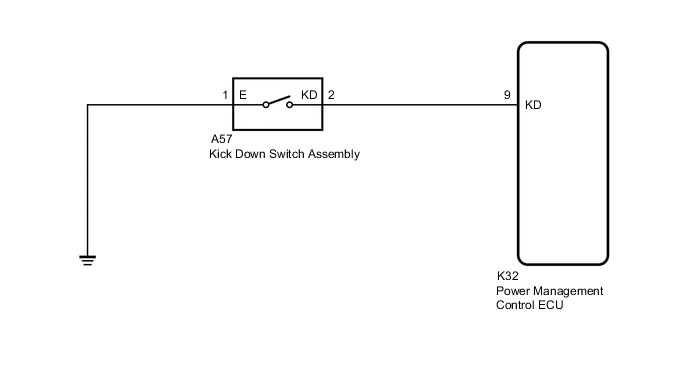
PROCEDURE
-
READ VALUE USING GTS (KICK DOWN SWITCH STATUS)
-
Connect the GTS to the DLC3.
-
Turn the power switch on (IG).
-
Enter the following menus: Powertrain / Hybrid Control / Data List / Kick Down Switch Status.
Powertrain > Hybrid Control > Data ListTester Display Kick Down Switch Status -
Read the value displayed on the GTS.
Powertrain > Hybrid Control > Data ListTester Display Measurement Item Range Normal Condition Kick Down Switch Status Kick down switch signal ON or OFF Accelerator pedal is depressed all the way down:ON
Accelerator pedal is released:OFF
Result Result Proceed to The GTS display changes according to the accelerator pedal operation. A The GTS display does not change according to the accelerator pedal operation. B -
Turn the power switch off.
A 
PROCEED TO NEXT SUSPECTED AREA SHOWN IN PROBLEM SYMPTOMS TABLE Click here
B 
-
-
CHECK CONNECTOR CONNECTION CONDITION (KICK DOWN SWITCH CONNECTOR)
-
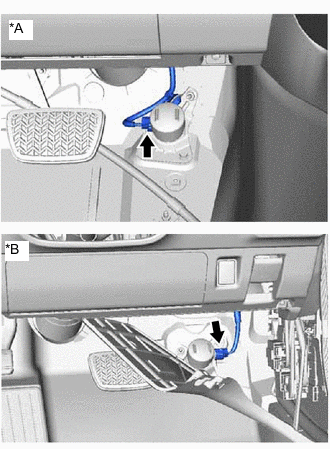
*A for LHD *B for RHD Check the connector connections and contact pressure of the relevant terminals for the kick down switch assembly connector
OK The connectors are connected securely and there are no contact pressure problems. Result Proceed to OK NG
NG
CONNECT SECURELY
OK
-
-
CHECK POWER MANAGEMENT CONTROL ECU
-
Disconnect the A57 kick down switch assembly connector.
-
Turn the power switch on (IG).
-
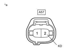
*a Front view of wire harness connector
(to Kick Down Switch Assembly)
Measure the voltage according to the value(s) in the table below.
Standard Voltage Tester Connection Condition Specified Condition A57-2 (KD) - Body ground Power switch on (IG) 11 to 14 V -
Turn the power switch off.
-
Reconnect the A57 kick down switch assembly connector.
Result Proceed to OK NG
NG 
CHECK HARNESS AND CONNECTOR (POWER MANAGEMENT CONTROL ECU - KICK DOWN SWITCH ASSEMBLY) Click here
OK
-
-
INSPECT KICK DOWN SWITCH ASSEMBLY
-
Remove the kick down switch assembly.
-
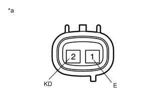
*a Component without harness connected
(Kick Down Switch Assembly)
Measure the resistance according to the value(s) in the table below.
Standard Resistance Tester Connection Condition Specified Condition 1 (E) - 2 (KD) Kick down switch assembly pushed Below 1 Ω 1 (E) - 2 (KD) Kick down switch assembly not pushed 10 kΩ or higher -
Install the kick down switch assembly.
Result Proceed to OK NG
NG
REPLACE KICK DOWN SWITCH ASSEMBLY Click here
OK
-
-
CHECK HARNESS AND CONNECTOR (KICK DOWN SWITCH ASSEMBLY - BODY GROUND)
-
Disconnect the A57 kick down switch assembly connector.
-
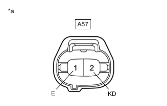
*a Front view of wire harness connector
(to Kick Down Switch Assembly)
Measure the resistance according to the value(s) in the table below.
Standard Resistance Tester Connection Condition Specified Condition A57-1 (E) - A57-2 (KD) Power switch off Below 1 Ω -
Reconnect the A57 kick down switch assembly connector.
Result Proceed to OK NG
OK
REPLACE POWER MANAGEMENT CONTROL ECU Click here
NG
REPAIR OR REPLACE HARNESS OR CONNECTOR
-
-
CHECK HARNESS AND CONNECTOR (POWER MANAGEMENT CONTROL ECU - KICK DOWN SWITCH ASSEMBLY)
-
Disconnect the K32 power management control ECU connector.
-
Disconnect the A57 kick down switch assembly connector.
-

*a Rear view of wire harness connector
(to Power Management Control ECU)
*b Front view of wire harness connector
(to Kick Down Switch Assembly)
Measure the resistance according to the value(s) in the table below.
Standard Resistance Tester Connection Condition Specified Condition K32-9 (KD) - A57-2 (KD) Power switch off Below 1 Ω K32-9 (KD) or A57-2 (KD) - Body ground Power switch off 10 kΩ or higher -
Reconnect the A57 kick down switch assembly connector.
-
Reconnect the K32 power management control ECU connector.
Result Proceed to OK NG
OK
REPLACE POWER MANAGEMENT CONTROL ECU Click here
NG
REPAIR OR REPLACE HARNESS OR CONNECTOR
-