HYBRID CONTROL SYSTEM, Diagnostic DTC:U0110-160
| DTC Code | DTC Name |
|---|---|
| U0110-160 | Lost Communication with Drive Motor Control Module "A" |
DESCRIPTION
The MG ECU, which is built into in the inverter with converter assembly, controls motor (MG2) based on commands from the power management control ECU.
The motor generator control ECU (MG ECU) monitors communication data and detects malfunctions.
A communication error between the MG ECU and power management control ECU is detected.
| DTC No. | Detection Item | DTC Detection Condition | Trouble Area | MIL | Warning Indicate |
|---|---|---|---|---|---|
| U0110-160 | Lost Communication with Drive Motor Control Module "A" | Error in signal transmission to the inverter with converter assembly (MG ECU) via serial communication (no transmission, out of communication standard) (1 trip detection logic) |
|
Does not come on | Master Warning Light: Comes on |
CAUTION / NOTICE / HINT
CAUTION:
-
Before inspecting the high-voltage system or disconnecting the low voltage connector of the inverter with converter assembly, take safety precautions such as wearing insulated gloves and removing the service plug grip to prevent electrical shocks. After removing the service plug grip, put it in your pocket to prevent other technicians from accidentally reconnecting it while you are working on the high-voltage system.
-
After removing the service plug grip, wait for at least 10 minutes before touching any of the high-voltage connectors or terminals. After waiting for 10 minutes, check the voltage at the terminals in the inspection point in the inverter with converter assembly. The voltage should be 0 V before beginning work.
Tech Tips
Waiting for at least 10 minutes is required to discharge the high-voltage capacitor inside the inverter with converter assembly.
Note
-
After turning the power switch off, waiting time may be required before disconnecting the cable from the negative (-) auxiliary battery terminal. Therefore, make sure to read the disconnecting the cable from the negative (-) auxiliary battery terminal notices before proceeding with work.
-
If DTC U0110-160 was stored due to incomplete engagement of the connectors, and the system returns to normal when the power switch is turned on (IG) after clearing the DTCs, DTC P324E-788 will be stored. Proceed to troubleshooting without considering DTC P324E-788.
Tech Tips
After the repair, clear the DTCs and perform the following procedure to check that DTCs are not output.
-
Turn the power switch on (IG) and wait for 2 minutes or more.
PROCEDURE
-
CLEAR DTC
Result Proceed to NEXT
-
Connect the GTS to the DLC3.
-
Turn the power switch on (IG).
-
Enter the following menus: Powertrain / Hybrid Control / Trouble Codes.
-
Read and record the DTCs and freeze frame data.
Powertrain > Hybrid Control > Trouble Codes -
Clear the DTCs and freeze frame data.
Powertrain > Hybrid Control > Clear DTCs -
Turn the power switch off.
Result Proceed to NEXT
NEXT 
-
-
CHECK DTC OUTPUT (HYBRID CONTROL)
-
Connect the GTS to the DLC3.
-
Turn the power switch on (IG).
-
Enter the following menus: Powertrain / Hybrid Control / Trouble Codes.
-
Check for DTCs.
Powertrain > Hybrid Control > Trouble CodesResult Proceed to U0110-160 is output. U0110-160 is not output. -
Turn the power switch off.
U0110-160 is not output. 
CHECK FOR INTERMITTENT PROBLEMS Click here
U0110-160 is output.
-
-
CHECK INVERTER WITH CONVERTER ASSEMBLY (GENERATOR CABLE CONNECTION CONDITION)
Result Result Proceed to The terminals are connected securely and there are no contact problems. There are no arc marks. A The terminals are not connected securely and there is a contact problem. There are arc marks. B The terminals are not connected securely and there is a contact problem. There are no arc marks. C The terminals are connected securely and there are no contact problems. There are arc marks. B CAUTION:
Be sure to wear insulated gloves.
-
Check that the service plug grip is not installed.
Note
After removing the service plug grip, do not turn the power switch on (READY), unless instructed by the repair manual because this may cause a malfunction.
-
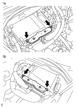
*A for LHD *B for RHD for Type A:
-
Remove the inverter cover from the inverter with converter assembly.
-
-
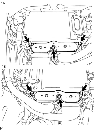
*A for LHD *B for RHD for Type B:
-
Remove the inverter cover from the inverter with converter assembly.
-
-
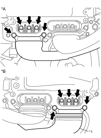
*A for LHD *B for RHD *1 Generator Cable
(Inverter with Converter Assembly Side)
Check that the bolts for the generator cable are tightened to the specified torque, the generator cable is connected securely, and there are no contact problems.
Specified Condition T = 8.0 N*m (82 kgf*cm, 71 in.*lbf) Note
Make sure that the tightening torque of the bolt is between 6.4 and 9.6 N*m (65 and 98 kgf*cm, 57 and 85 in.*lbf).
-
Disconnect the generator cable from the inverter with converter assembly.
-
Check for arc marks at the terminals for the generator cable.
Result Result Proceed to The terminals are connected securely and there are no contact problems. There are no arc marks. A The terminals are not connected securely and there is a contact problem. There are arc marks. B The terminals are not connected securely and there is a contact problem. There are no arc marks. C The terminals are connected securely and there are no contact problems. There are arc marks. B -
Connect the generator cable to the inverter with converter assembly.
-
Install the inverter cover.
B
REPLACE MALFUNCTIONING PARTS
C
CONNECT SECURELY
A
-
-
CHECK INVERTER WITH CONVERTER ASSEMBLY (MOTOR CABLE CONNECTION CONDITION)
Result Result Proceed to The terminals are connected securely and there are no contact problems. There are no arc marks. A The terminals are not connected securely and there is a contact problem. There are arc marks. B The terminals are not connected securely and there is a contact problem. There are no arc marks. C The terminals are connected securely and there are no contact problems. There are arc marks. B CAUTION:
Be sure to wear insulated gloves.
-
Check that the service plug grip is not installed.
Note
After removing the service plug grip, do not turn the power switch on (READY), unless instructed by the repair manual because this may cause a malfunction.
-
*A for LHD *B for RHD for Type A:
-
Remove the inverter cover from the inverter with converter assembly.
-
-
*A for LHD *B for RHD for Type B:
-
Remove the inverter cover from the inverter with converter assembly.
-
-

*A for LHD *B for RHD *1 Motor Cable
(Inverter with Converter Assembly Side)
Check that the bolts for the motor cable are tightened to the specified torque, the motor cable is connected securely, and there are no contact problems.
Specified Condition T = 8.0 N*m (82 kgf*cm, 71 in.*lbf) Note
Make sure that the tightening torque of the bolt is between 6.4 and 9.6 N*m (65 and 98 kgf*cm, 57 and 85 in.*lbf).
-
Disconnect the motor cable from the inverter with converter assembly.
-
Check for arc marks at the terminals for the motor cable.
Result Result Proceed to The terminals are connected securely and there are no contact problems. There are no arc marks. A The terminals are not connected securely and there is a contact problem. There are arc marks. B The terminals are not connected securely and there is a contact problem. There are no arc marks. C The terminals are connected securely and there are no contact problems. There are arc marks. B -
Connect the motor cable to the inverter with converter assembly.
-
Install the inverter cover.
B
REPLACE MALFUNCTIONING PARTS
C
CONNECT SECURELY
A
-
-
CHECK HYBRID VEHICLE TRANSMISSION ASSEMBLY (MG1)
Result Proceed to OK NG CAUTION:
Be sure to wear insulated gloves.
-
Check that the service plug grip is not installed.
Note
After removing the service plug grip, do not turn the power switch on (READY), unless instructed by the repair manual because this may cause a malfunction.
-
*A for LHD *B for RHD for Type A:
-
Remove the inverter cover from the inverter with converter assembly.
-
-
*A for LHD *B for RHD for Type B:
-
Remove the inverter cover from the inverter with converter assembly.
-
-
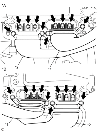
*A for LHD *B for RHD *1 Motor Cable
(Inverter with Converter Assembly Side)
*2 Generator Cable
(Inverter with Converter Assembly Side)
Disconnect the generator cable and motor cable from the inverter with converter assembly.
-
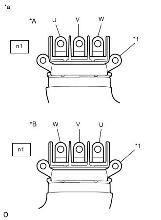
*A for LHD *B for RHD *1 Shield Ground *a Generator Cable
(Inverter with Converter Assembly Side)
Check generator (MG1) for an interphase short using a milliohmmeter.
-
Using a milliohmmeter, measure the resistance according to the value(s) in the table below.
Tech Tips
If the generator (MG1) temperature is high, the resistance will vary greatly from the specification. Therefore, measure the resistance at least 8 hours after the vehicle is stopped.
Standard Resistance for LHD Tester Connection Condition Specified Condition n1-3 (W) -n1-1 (U) Power switch off 59.2 to 65.2 mΩ n1-2 (V) - n1-3 (W) Power switch off 62.2 to 68.2 mΩ n1-1 (U) - n1-2 (V) Power switch off 59.2 to 65.2 mΩ for RHD Tester Connection Condition Specified Condition n1-1 (W) -n1-3 (U) Power switch off 59.0 to 65.0 mΩ n1-2 (V) - n1-1 (W) Power switch off 61.9 to 67.9 mΩ n1-3 (U) - n1-2 (V) Power switch off 59.0 to 65.0 mΩ Tech Tips
To correct the variation of the measured resistance due to temperature, use the following formula to calculate the resistance at 20°C (68° F).
R20 = Rt / {1 + 0.00393 X (T - 20)}
The calculation is based on the following:
R20: Resistance at 20°C (68° F) (mΩ)
Rt: Measured resistance (mΩ)
T: Temperature when the resistance is measured (°C)
-
-
When checking for a short circuit between motor phases without using a milliohmmeter.
Note
The motor generates current when wheels are rotated by hand. Before performing the inspection, wrap the motor cable terminals with insulation tape.
Tech Tips
A short circuit between the motor phases can be checked simply without using a milliohmmeter.
-
Connect the cable to the negative (-) auxiliary battery terminal.
-
Turn the power switch on (IG).
Note
Turning the power switch on (IG) with the service plug grip removed causes other DTCs to be stored. Clear the DTCs after performing this inspection.
-
Move the shift lever to N.
-
Lift up the vehicle.
-
Rotate the rear wheels in the same direction simultaneously by hand.
Standard Left and right wheels rotate smoothly (No short circuit between phases) Tech Tips
If a short circuit exists between the motor phases, the rear wheels do not rotate smoothly (some resistance is felt).
-
Move the shift lever to P.
-
Lower the vehicle.
-
Turn the power switch off.
-
Disconnect the cable from the negative (-) auxiliary battery terminal.
-
-
Using a megohmmeter set to 500 V, measure the resistance according to the value(s) in the table below.
Note
Be sure to set the megohmmeter to 500 V when performing this test. Using a setting higher than 500 V can result in damage to the component being inspected.
Standard Resistance for LHD Tester Connection Condition Specified Condition n1-3 (W) - Body ground and shield ground Power switch off 100 MΩ or higher n1-2 (V) - Body ground and shield ground Power switch off 100 MΩ or higher n1-1 (U) - Body ground and shield ground Power switch off 100 MΩ or higher for RHD Tester Connection Condition Specified Condition n1-1 (W) - Body ground and shield ground Power switch off 100 MΩ or higher n1-2 (V) - Body ground and shield ground Power switch off 100 MΩ or higher n1-3 (U) - Body ground and shield ground Power switch off 100 MΩ or higher -
Measure the resistance according to the value(s) in the table below.
Tech Tips
Perform this procedure only when checking for a short circuit between motor phases without using a milliohmmeter.
Standard Resistance for LHD Tester Connection Condition Specified Condition n1-3(W) - n1-2(V) Power switch off Below 1 Ω n1-2(V) - n1-1(U) Power switch off Below 1 Ω for RHD Tester Connection Condition Specified Condition n1-1(W) - n1-2(V) Power switch off Below 1 Ω n1-2(V) - n1-3(U) Power switch off Below 1 Ω -
Connect the generator cable and motor cable.
-
Install the inverter cover.
Result Proceed to OK NG
NG 
CHECK HYBRID VEHICLE TRANSMISSION ASSEMBLY (GENERATOR CABLE CONNECTION CONDITION) Click here
OK
-
-
CHECK HYBRID VEHICLE TRANSMISSION ASSEMBLY (MG2)
Result Proceed to OK NG CAUTION:
Be sure to wear insulated gloves.
-
Check that the service plug grip is not installed.
Note
After removing the service plug grip, do not turn the power switch on (READY), unless instructed by the repair manual because this may cause a malfunction.
-
*A for LHD *B for RHD for Type A:
-
Remove the inverter cover from the inverter with converter assembly.
-
-
*A for LHD *B for RHD for Type B:
-
Remove the inverter cover from the inverter with converter assembly.
-
-
*A for LHD *B for RHD *1 Motor Cable
(Inverter with Converter Assembly Side)
*2 Generator Cable
(Inverter with Converter Assembly Side)
Disconnect the generator cable and motor cable from the inverter with converter assembly.
-

*A for LHD *B for RHD *1 Shield Ground *a Motor Cable
(Inverter with Converter Assembly Side)
Check motor (MG2) for an interphase short using a milliohmmeter.
-
Using a milliohmmeter, measure the resistance according to the value(s) in the table below.
Tech Tips
If the motor (MG2) temperature is high, the resistance will vary greatly from the specification. Therefore, measure the resistance at least 8 hours after the vehicle is stopped.
Standard Resistance for LHD Tester Connection Condition Specified Condition m3-3 (W) - m3-1 (U) Power switch off 47.0 to 51.8 mΩ m3-2 (V) - m3-3 (W) Power switch off 47.3 to 52.1 mΩ m3-1 (U) - m3-2 (V) Power switch off 47.1 to 51.9 mΩ for RHD Tester Connection Condition Specified Condition m1-1 (W) - m1-3 (U) Power switch off 47.0 to 51.8 mΩ m1-2 (V) - m1-1 (W) Power switch off 47.3 to 52.1 mΩ m1-3 (U) - m1-2 (V) Power switch off 47.1 to 51.9 mΩ Tech Tips
To correct the variation of the measured resistance due to temperature, use the following formula to calculate the resistance at 20°C (68° F).
R20 = Rt / {1 + 0.00393 X (T - 20)}
The calculation is based on the following:
R20: Resistance at 20°C (68° F) (mΩ)
Rt: Measured resistance (mΩ)
T: Temperature when the resistance is measured (°C)
-
-
When checking for a short circuit between motor phases without using a milliohmmeter.
Note
The motor generates current when wheels are rotated by hand. Before performing the inspection, wrap the motor cable terminals with insulation tape.
Tech Tips
A short circuit between the motor phases can be checked simply without using a milliohmmeter.
-
Connect the cable to the negative (-) auxiliary battery terminal.
-
Turn the power switch on (IG).
Note
Turning the power switch on (IG) with the service plug grip removed causes other DTCs to be stored. Clear the DTCs after performing this inspection.
-
Move the shift lever to N.
-
Lift up the vehicle.
-
Rotate the rear wheels in the same direction simultaneously by hand.
Standard Left and right wheels rotate smoothly (No short circuit between phases) Tech Tips
If a short circuit exists between the motor phases, the rear wheels do not rotate smoothly (some resistance is felt).
-
Move the shift lever to P.
-
Lower the vehicle.
-
Turn the power switch off.
-
Disconnect the cable from the negative (-) auxiliary battery terminal.
-
-
Using a megohmmeter set to 500 V, measure the resistance according to the value(s) in the table below.
Note
Be sure to set the megohmmeter to 500 V when performing this test. Using a setting higher than 500 V can result in damage to the component being inspected.
Standard Resistance for LHD Tester Connection Condition Specified Condition m3-3 (W) - Body ground and shield ground Power switch off 100 MΩ or higher m3-2 (V) - Body ground and shield ground Power switch off 100 MΩ or higher m3-1 (U) - Body ground and shield ground Power switch off 100 MΩ or higher for RHD Tester Connection Condition Specified Condition m1-1 (W) - Body ground and shield ground Power switch off 100 MΩ or higher m1-2 (V) - Body ground and shield ground Power switch off 100 MΩ or higher m1-3 (U) - Body ground and shield ground Power switch off 100 MΩ or higher -
Measure the resistance according to the value(s) in the table below.
Tech Tips
Perform this procedure only when checking for a short circuit between motor phases without using a milliohmmeter.
Standard Resistance for LHD Tester Connection Condition Specified Condition m3-3(W) - m3-2(V) Power switch off Below 1 Ω m3-2(V) - m3-1(U) Power switch off Below 1 Ω for RHD Tester Connection Condition Specified Condition m1-1(W) - m1-2(V) Power switch off Below 1 Ω m1-2(V) - m1-3(U) Power switch off Below 1 Ω -
Connect the generator cable and motor cable.
-
Install the inverter cover.
Result Proceed to OK NG
NG
CHECK HYBRID VEHICLE TRANSMISSION ASSEMBLY (MOTOR CABLE CONNECTION CONDITION) Click here
OK
-
-
CHECK POWER MANAGEMENT CONTROL ECU (CHECK WAVEFORM)
-
Connect an oscilloscope between the power management control ECU terminals specified in the following table.
-
Turn the power switch on (IG).
-
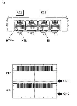
*a Component with harness connected
(Power Management Control ECU)
Measure the waveform.
Item Contents Tester Connection CH1: A62-34 (HTM+) - K32-6 (E1)
CH2: A62-33 (HTM-) - K32-6 (E1)
Equipment Setting 1 V/DIV., 200 μs./DIV. Condition Power switch on (IG) Result Proceed to The waveform appears as shown in the illustration. The waveform differs from the one shown in the illustration. Tech Tips
-
Inspect with the connector connected.
-
If pulses are generated, the shape of the waveform can be assumed to be normal.
-
The shape of the waveform may vary according to communication conditions.
-
-
Turn the power switch off.
The waveform differs from the one shown in the illustration.
CHECK HARNESS AND CONNECTOR (POWER MANAGEMENT CONTROL ECU - INVERTER WITH CONVERTER ASSEMBLY) Click here
The waveform appears as shown in the illustration.
-
-
CHECK POWER MANAGEMENT CONTROL ECU (CHECK WAVEFORM)
Result Proceed to The waveform appears as shown in the illustration. The waveform differs from the one shown in the illustration.
-
Connect an oscilloscope between the power management control ECU terminals specified in the following table.
-
Turn the power switch on (IG).
-
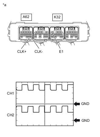
*a Component with harness connected
(Power Management Control ECU)
Measure the waveform.
Item Contents Tester Connection CH1: A62-28 (CLK+) - K32-6 (E1)
CH2: A62-29 (CLK-) - K32-6 (E1)
Equipment Setting 1 V/DIV., 1 μs./DIV. Condition Power switch on (IG) Result Proceed to The waveform appears as shown in the illustration. The waveform differs from the one shown in the illustration. Tech Tips
-
Inspect with the connector connected.
-
If pulses are generated, the shape of the waveform can be assumed to be normal.
-
The shape of the waveform may vary according to communication conditions.
-
-
Turn the power switch off.
The waveform differs from the one shown in the illustration.
CHECK HARNESS AND CONNECTOR (POWER MANAGEMENT CONTROL ECU - INVERTER WITH CONVERTER ASSEMBLY) Click here
The waveform appears as shown in the illustration.
-
-
CHECK POWER MANAGEMENT CONTROL ECU (CHECK WAVEFORM)
Result Proceed to The waveform appears as shown in the illustration. The waveform differs from the one shown in the illustration.
-
Connect an oscilloscope between the power management control ECU terminals specified in the following table.
-
Turn the power switch on (IG).
-
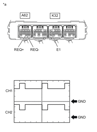
*a Component with harness connected
(Power Management Control ECU)
Measure the waveform.
Item Contents Tester Connection CH1: A62-32 (REQ+) - K32-6 (E1)
CH2: A62-31 (REQ-) - K32-6 (E1)
Equipment Setting 1 V/DIV., 1 ms./DIV. Condition Power switch on (IG) Result Proceed to The waveform appears as shown in the illustration. The waveform differs from the one shown in the illustration. Tech Tips
-
Inspect with the connector connected.
-
If pulses are generated, the shape of the waveform can be assumed to be normal.
-
The shape of the waveform may vary according to communication conditions.
-
-
Turn the power switch off.
The waveform appears as shown in the illustration.
REPLACE INVERTER WITH CONVERTER ASSEMBLY Click here
The waveform differs from the one shown in the illustration.
-
-
CHECK HARNESS AND CONNECTOR (POWER MANAGEMENT CONTROL ECU - INVERTER WITH CONVERTER ASSEMBLY)
Result Proceed to OK NG CAUTION:
Be sure to wear insulated gloves.
-
Check that the service plug grip is not installed.
Note
After removing the service plug grip, do not turn the power switch on (READY), unless instructed by the repair manual because this may cause a malfunction.
-
Disconnect the A62 power management control ECU connector.
-
Disconnect the A28*1 or A29*2 inverter with converter assembly connector.
-
*1: for LHD
-
*2: for RHD
-
-
Connect the cable to the negative (-) auxiliary battery terminal.
-
Turn the power switch on (IG).
-
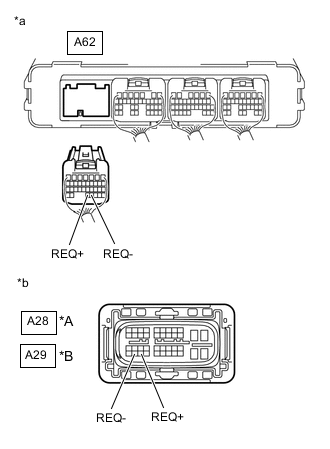
*A for LHD *B for RHD *a Rear view of wire harness connector
(to Power Management Control ECU)
*b Front view of wire harness connector
(to Inverter with Converter Assembly)
Measure the voltage according to the value(s) in the table below.
Standard Voltage Tester Connection Condition Specified Condition A62-32 (REQ+) - Body ground Power switch on (IG) Below 1 V A62-31 (REQ-) - Body ground Power switch on (IG) Below 1 V Note
Turning the power switch on (IG) with the power management control ECU connector and the inverter with converter assembly disconnected causes other DTCs to be stored. Clear the DTCs after performing this inspection.
-
Turn the power switch off.
-
Disconnect the cable from the negative (-) auxiliary battery terminal.
-
Measure the resistance according to the value(s) in the table below.
Standard Resistance (Check for Open) for LHD Tester Connection Condition Specified Condition A62-32 (REQ+) - A28-34 (REQ+) Power switch off Below 1 Ω A62-31 (REQ-) - A28-33 (REQ-) Power switch off Below 1 Ω for RHD Tester Connection Condition Specified Condition A62-32 (REQ+) - A29-34 (REQ+) Power switch off Below 1 Ω A62-31 (REQ-) - A29-33 (REQ-) Power switch off Below 1 Ω Standard Resistance (Check for Short) for LHD Tester Connection Condition Specified Condition A62-32 (REQ+) or A28-34 (REQ+) - Body ground and other terminals Power switch off 10 kΩ or higher A62-31 (REQ-) or A28-33 (REQ-) - Body ground and other terminals Power switch off 10 kΩ or higher for RHD Tester Connection Condition Specified Condition A62-32 (REQ+) or A29-34 (REQ+) - Body ground and other terminals Power switch off 10 kΩ or higher A62-31 (REQ-) or A29-33 (REQ-) - Body ground and other terminals Power switch off 10 kΩ or higher -
Reconnect the A28*1 or A29*2 inverter with converter assembly connector.
-
*1: for LHD
-
*2: for RHD
-
-
Reconnect the A62 power management control ECU connector.
Result Proceed to OK NG
NG
REPAIR OR REPLACE HARNESS OR CONNECTOR
OK
-
-
CHECK INVERTER WITH CONVERTER ASSEMBLY
Result Proceed to OK NG
-
Disconnect the A62 power management control ECU connector.
-
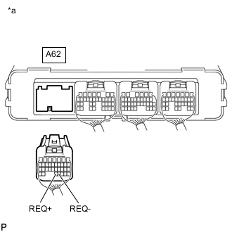
*a Rear view of wire harness connector
(to Power Management Control ECU)
Measure the resistance according to the value(s) in the table below.
Standard Resistance Tester Connection Condition Specified Condition A62-32 (REQ+) - A62-31 (REQ-) Power switch off 80 to 170 Ω -
Reconnect the A62 power management control ECU connector.
Result Proceed to OK NG
OK
REPLACE POWER MANAGEMENT CONTROL ECU Click here
NG
REPLACE INVERTER WITH CONVERTER ASSEMBLY Click here
-
-
CHECK HARNESS AND CONNECTOR (POWER MANAGEMENT CONTROL ECU - INVERTER WITH CONVERTER ASSEMBLY)
Result Proceed to OK NG CAUTION:
Be sure to wear insulated gloves.
-
Check that the service plug grip is not installed.
Note
After removing the service plug grip, do not turn the power switch on (READY), unless instructed by the repair manual because this may cause a malfunction.
-
Disconnect the A62 power management control ECU connector.
-
Disconnect the A28*1 or A29*2 inverter with converter assembly connector.
-
*1: for LHD
-
*2: for RHD
-
-
Connect the cable to the negative (-) auxiliary battery terminal.
-
Turn the power switch on (IG).
-
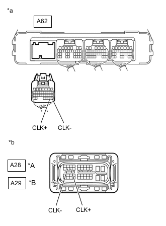
*A for LHD *B for RHD *a Rear view of wire harness connector
(to Power Management Control ECU)
*b Front view of wire harness connector
(to Inverter with Converter Assembly)
Measure the voltage according to the value(s) in the table below.
Standard Voltage Tester Connection Condition Specified Condition A62-29 (CLK+) - Body ground Power switch on (IG) Below 1 V A62-28 (CLK-) - Body ground Power switch on (IG) Below 1 V Note
Turning the power switch on (IG) with the power management control ECU connector and the inverter with converter assembly disconnected causes other DTCs to be stored. Clear the DTCs after performing this inspection.
-
Turn the power switch off.
-
Disconnect the cable from the negative (-) auxiliary battery terminal.
-
Measure the resistance according to the value(s) in the table below.
Standard Resistance (Check for Open) for LHD Tester Connection Condition Specified Condition A62-29 (CLK+) - A28-14 (CLK+) Power switch off Below 1 Ω A62-28 (CLK-) - A28-13 (CLK-) Power switch off Below 1 Ω for RHD Tester Connection Condition Specified Condition A62-29 (CLK+) - A29-14 (CLK+) Power switch off Below 1 Ω A62-28 (CLK-) - A29-13 (CLK-) Power switch off Below 1 Ω Standard Resistance (Check for Short) for LHD Tester Connection Condition Specified Condition A62-29 (CLK+) or A28-14 (CLK+) - Body ground and other terminals Power switch off 10 kΩ or higher A62-28 (CLK-) or A28-13 (CLK-) - Body ground and other terminals Power switch off 10 kΩ or higher for RHD Tester Connection Condition Specified Condition A62-29 (CLK+) or A29-14 (CLK+) - Body ground and other terminals Power switch off 10 kΩ or higher A62-28 (CLK-) or A29-13 (CLK-) - Body ground and other terminals Power switch off 10 kΩ or higher -
Reconnect the A28*1 or A29*2 inverter with converter assembly connector.
-
*1: for LHD
-
*2: for RHD
-
-
Reconnect the A62 power management control ECU connector.
Result Proceed to OK NG
NG
REPAIR OR REPLACE HARNESS OR CONNECTOR
OK
-
-
CHECK INVERTER WITH CONVERTER ASSEMBLY
Result Proceed to OK NG
-
Disconnect the A62 power management control ECU connector.
-
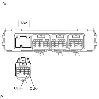
*a Rear view of wire harness connector
(to Power Management Control ECU)
Measure the resistance according to the value(s) in the table below.
Standard Resistance Tester Connection Condition Specified Condition A62-29 (CLK+) - A62-28 (CLK-) Power switch off 80 to 170 Ω -
Reconnect the A62 power management control ECU connector.
Result Proceed to OK NG
OK
REPLACE POWER MANAGEMENT CONTROL ECU Click here
NG
REPLACE INVERTER WITH CONVERTER ASSEMBLY Click here
-
-
CHECK HARNESS AND CONNECTOR (POWER MANAGEMENT CONTROL ECU - INVERTER WITH CONVERTER ASSEMBLY)
CAUTION:
Be sure to wear insulated gloves.
-
Check that the service plug grip is not installed.
Note
After removing the service plug grip, do not turn the power switch on (READY), unless instructed by the repair manual because this may cause a malfunction.
-
Disconnect the A62 power management control ECU connector.
-
Disconnect the A28*1 or A29*2 inverter with converter assembly connector.
-
*1: for LHD
-
*2: for RHD
-
-
Connect the cable to the negative (-) auxiliary battery terminal.
-
Turn the power switch on (IG).
-
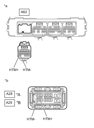
*A for LHD *B for RHD *a Rear view of wire harness connector
(to Power Management Control ECU)
*b Front view of wire harness connector
(to Inverter with Converter Assembly)
Measure the voltage according to the value(s) in the table below.
Standard Voltage Tester Connection Condition Specified Condition A62-34 (HTM+) - Body ground Power switch on (IG) Below 1 V A62-33 (HTM-) - Body ground Power switch on (IG) Below 1 V Note
Turning the power switch on (IG) with the connector of the power management control ECU and the inverter with converter assembly disconnected causes other DTCs to be stored. Clear the DTCs after performing this inspection.
-
Turn the power switch off.
-
Disconnect the cable from the negative (-) auxiliary battery terminal.
-
Measure the resistance according to the value(s) in the table below.
Standard Resistance (Check for Open) for LHD Tester Connection Condition Specified Condition A62-34 (HTM+) - A28-23 (HTM+) Power switch off Below 1 Ω A62-33 (HTM-) - A28-22 (HTM-) Power switch off Below 1 Ω for RHD Tester Connection Condition Specified Condition A62-34 (HTM+) - A29-23 (HTM+) Power switch off Below 1 Ω A62-33 (HTM-) - A29-22 (HTM-) Power switch off Below 1 Ω Standard Resistance (Check for Short) for LHD Tester Connection Condition Specified Condition A62-34 (HTM+) or A28-23 (HTM+) - Body ground and other terminals Power switch off 10 kΩ or higher A62-33 (HTM-) or A28-22 (HTM-) - Body ground and other terminals Power switch off 10 kΩ or higher for RHD Tester Connection Condition Specified Condition A62-34 (HTM+) or A29-23 (HTM+) - Body ground and other terminals Power switch off 10 kΩ or higher A62-33 (HTM-) or A29-22 (HTM-) - Body ground and other terminals Power switch off 10 kΩ or higher -
Reconnect the A28*1 or A29*2 inverter with converter assembly connector.
-
*1: for LHD
-
*2: for RHD
-
-
Reconnect the A62 power management control ECU connector.
Result Proceed to OK NG
NG
REPAIR OR REPLACE HARNESS OR CONNECTOR
OK
-
-
CHECK INVERTER WITH CONVERTER ASSEMBLY
-
Disconnect the A62 power management control ECU connector.
-
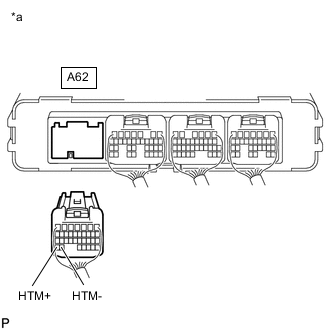
*a Rear view of wire harness connector
(to Power Management Control ECU)
Measure the resistance according to the value(s) in the table below.
Standard Resistance Tester Connection Condition Specified Condition A62-34 (HTM+) - A62-33 (HTM-) Power switch off 80 to 170 Ω -
Reconnect the A62 power management control ECU connector.
Result Proceed to OK NG
OK
REPLACE POWER MANAGEMENT CONTROL ECU Click here
NG
REPLACE INVERTER WITH CONVERTER ASSEMBLY Click here
-
-
CHECK HYBRID VEHICLE TRANSMISSION ASSEMBLY (MOTOR CABLE CONNECTION CONDITION)
Result Result Proceed to The terminals are connected securely and there are no contact problems. There are no arc marks. A The terminals are not connected securely and there is a contact problem. There are arc marks. B The terminals are not connected securely and there is a contact problem. There are no arc marks. C The terminals are connected securely and there are no contact problems. There are arc marks. B CAUTION:
Be sure to wear insulated gloves.
-
Check that the service plug grip is not installed.
Note
After removing the service plug grip, do not turn the power switch on (READY), unless instructed by the repair manual because this may cause a malfunction.
-
Remove the hybrid vehicle transmission assembly.
-
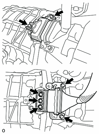
Check that the bolts for the motor cable are tightened to the specified torque, the motor cable is connected securely, and there are no contact problems.
Specified Condition T = 8.0 N*m (82 kgf*cm, 71 in.*lbf) Note
Make sure that the tightening torque of the bolt is between 6.4 and 9.6 N*m (65 and 98 kgf*cm, 57 and 85 in.*lbf).
-
Disconnect the motor cable from the hybrid vehicle transmission assembly.
-
Check for arc marks at the terminals for the motor cable.
Result Result Proceed to The terminals are connected securely and there are no contact problems. There are no arc marks. A The terminals are not connected securely and there is a contact problem. There are arc marks. B The terminals are not connected securely and there is a contact problem. There are no arc marks. C The terminals are connected securely and there are no contact problems. There are arc marks. B -
Connect the motor cable to the hybrid vehicle transmission assembly.
-
Install the hybrid vehicle transmission assembly.
B
REPLACE MALFUNCTIONING PARTS
C
CONNECT SECURELY
A
-
-
CHECK MOTOR CABLE
Result Proceed to OK NG CAUTION:
Be sure to wear insulated gloves.
-
Check that the service plug grip is not installed.
Note
After removing the service plug grip, do not turn the power switch on (READY), unless instructed by the repair manual because this may cause a malfunction.
-
Remove the motor cable.
-
Using a megohmmeter set to 500 V, measure the resistance according to the value(s) in the table below.
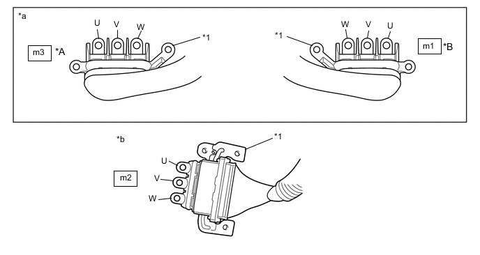
*A for LHD *B for RHD *1 Shield ground - - *a Motor Cable
(Inverter with Converter Assembly Side)
*b Motor Cable
(Hybrid Vehicle Transmission Assembly Side)
Note
Be sure to set the megohmmeter to 500 V when performing this test. Using a setting higher than 500 V can result in damage to the component being inspected.
Standard Resistance for LHD Tester Connection Condition Specified Condition m3-3 (W) - Body ground and shield ground Power switch off 100 MΩ or higher m3-2 (V) - Body ground and shield ground Power switch off 100 MΩ or higher m3-1 (U) - Body ground and shield ground Power switch off 100 MΩ or higher for RHD Tester Connection Condition Specified Condition m1-1 (W) - Body ground and shield ground Power switch off 100 MΩ or higher m1-2 (V) - Body ground and shield ground Power switch off 100 MΩ or higher m1-3 (U) - Body ground and shield ground Power switch off 100 MΩ or higher Note
Wrap the terminal of the motor cable with insulating tape to prevent them from coming into contact with body ground.
-
Measure the resistance according to the value(s) in the table below.
Standard Resistance for LHD Tester Connection Condition Specified Condition m3-3 (W) - m2-3 (U) Power switch off 100 MΩ or higher m3-2 (V) - m2-1 (W) Power switch off 100 MΩ or higher m3-1 (U) - m2-2 (V) Power switch off 100 MΩ or higher m3-3 (W) - m2-1 (W) Power switch off Below 1 Ω m3-2 (V) - m2-2 (V) Power switch off Below 1 Ω m3-1 (U) - m2-3 (U) Power switch off Below 1 Ω for RHD Tester Connection Condition Specified Condition m1-1 (W) - m2-3 (U) Power switch off 100 MΩ or higher m1-2 (V) - m2-1 (W) Power switch off 100 MΩ or higher m1-3 (U) - m2-2 (V) Power switch off 100 MΩ or higher m1-1 (W) - m2-1 (W) Power switch off Below 1 Ω m1-2 (V) - m2-2 (V) Power switch off Below 1 Ω m1-3 (U) - m2-3 (U) Power switch off Below 1 Ω -
Install the motor cable.
Result Proceed to OK NG
OK
REPLACE HYBRID VEHICLE TRANSMISSION ASSEMBLY Click here
NG
REPLACE MOTOR CABLE Click here
-
-
CHECK HYBRID VEHICLE TRANSMISSION ASSEMBLY (GENERATOR CABLE CONNECTION CONDITION)
Result Result Proceed to The terminals are connected securely and there are no contact problems. There are no arc marks. A The terminals are not connected securely and there is a contact problem. There are arc marks. B The terminals are not connected securely and there is a contact problem. There are no arc marks. C The terminals are connected securely and there are no contact problems. There are arc marks. B CAUTION:
Be sure to wear insulated gloves.
-
Check that the service plug grip is not installed.
Note
After removing the service plug grip, do not turn the power switch on (READY), unless instructed by the repair manual because this may cause a malfunction.
-
Remove the hybrid vehicle transmission assembly.
-
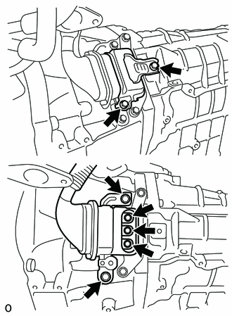
Check that the bolts for the generator cable are tightened to the specified torque, the generator cable is connected securely, and there are no contact problems.
Specified Condition T = 8.0 N*m (82 kgf*cm, 71 in.*lbf) Note
Make sure that the tightening torque of the bolt is between 6.4 and 9.6 N*m (65 and 98 kgf*cm, 57 and 85 in.*lbf).
-
Disconnect the generator cable from the hybrid vehicle transmission assembly.
-
Check for arc marks at the terminals for the generator cable.
Result Result Proceed to The terminals are connected securely and there are no contact problems. There are no arc marks. A The terminals are not connected securely and there is a contact problem. There are arc marks. B The terminals are not connected securely and there is a contact problem. There are no arc marks. C The terminals are connected securely and there are no contact problems. There are arc marks. B -
Connect the generator cable to the hybrid vehicle transmission assembly.
-
Install the hybrid vehicle transmission assembly.
B
REPLACE MALFUNCTIONING PARTS
C
CONNECT SECURELY
A
-
-
CHECK GENERATOR CABLE
Result Proceed to OK NG CAUTION:
Be sure to wear insulated gloves.
-
Check that the service plug grip is not installed.
Note
After removing the service plug grip, do not turn the power switch on (READY), unless instructed by the repair manual because this may cause a malfunction.
-
Remove the generator cable.
-
Using a megohmmeter set to 500 V, measure the resistance according to the value(s) in the table below.
Note
Be sure to set the megohmmeter to 500 V when performing this test. Using a setting higher than 500 V can result in damage to the component being inspected.
Standard Resistance for LHD Tester Connection Condition Specified Condition n1-3 (W) - Body ground and shield ground Power switch off 100 MΩ or higher n1-2 (V) - Body ground and shield ground Power switch off 100 MΩ or higher n1-1 (U) - Body ground and shield ground Power switch off 100 MΩ or higher for RHD Tester Connection Condition Specified Condition n1-1 (W) - Body ground and shield ground Power switch off 100 MΩ or higher n1-2 (V) - Body ground and shield ground Power switch off 100 MΩ or higher n1-3 (U) - Body ground and shield ground Power switch off 100 MΩ or higher 
*A for LHD *B for RHD *1 Shield ground - - *a Generator Cable
(Inverter with Converter Assembly Side)
*b Generator Cable
(Hybrid Vehicle Transmission Assembly Side)
Note
Wrap the terminal of the generator cable with insulating tape to prevent them from coming into contact with body ground.
-
Measure the resistance according to the value(s) in the table below.
Standard Resistance for LHD Tester Connection Condition Specified Condition n1-3 (W) - n2-1 (U) Power switch off 100 MΩ or higher n1-2 (V) - n2-3 (W) Power switch off 100 MΩ or higher n1-1 (U) - n2-2 (V) Power switch off 100 MΩ or higher n1-3 (W) - n2-3 (W) Power switch off Below 1 Ω n1-2 (V) - n2-2 (V) Power switch off Below 1 Ω n1-1 (U) - n2-1 (U) Power switch off Below 1 Ω for RHD Tester Connection Condition Specified Condition n1-1 (W) - n2-1 (U) Power switch off 100 MΩ or higher n1-2 (V) - n2-3 (W) Power switch off 100 MΩ or higher n1-3 (U) - n2-2 (V) Power switch off 100 MΩ or higher n1-1 (W) - n2-3 (W) Power switch off Below 1 Ω n1-2 (V) - n2-2 (V) Power switch off Below 1 Ω n1-3 (U) - n2-1 (U) Power switch off Below 1 Ω -
Install the generator cable.
Result Proceed to OK NG
OK
REPLACE HYBRID VEHICLE TRANSMISSION ASSEMBLY Click here
NG
REPLACE GENERATOR CABLE Click here
-