HYBRID CONTROL SYSTEM, Diagnostic DTC:P314A-828
| DTC Code | DTC Name |
|---|---|
| P314A-828 | Inverter Coolant Pump Speed Signal |
DESCRIPTION
Refer to the description for DTC P0C73-776.
| DTC No. | Detection Item | DTC Detection Condition | Trouble Area | MIL | Warning Indicate |
|---|---|---|---|---|---|
| P314A-828 | Inverter Coolant Pump Speed Signal | The water pump speed signal is not sent to the power management control ECU when the power switch is turned on (READY).*1 (1 trip detection logic) |
|
Comes on | Master Warning Light: Comes on |
-
*1: Malfunction (open, short to +B or short to ground) in the speed signal line from the inverter water pump assembly or inverter water pump assembly power source circuit malfunction is suspected.
| DTC No. | Data List |
|---|---|
| P314A-828 |
|
-
*2: This Data List item is related to the inverter water pump assembly.
| DTC No. | Active Test |
|---|---|
| P314A-828 | Activate the Water Pump*3 |
-
*3: This is an Active Test of the inverter water pump assembly.
CAUTION / NOTICE / HINT
Note
If DTC P0A78-284, 286, P0A7A-322, 324, P0A94-553 or 557 is output, replace the inverter with converter assembly after this inspection.
Tech Tips
After the repair, clear the DTCs and perform the following procedure to check that DTCs are not output.
-
Turn the power switch on (READY) and wait for 2 minutes or more.
PROCEDURE
-
CLEAR DTC
Result Proceed to NEXT
-
Connect the GTS to the DLC3.
-
Turn the power switch on (IG).
-
Enter the following menus: Powertrain / Hybrid Control / Trouble Codes.
-
Read and record the DTCs and freeze frame data.
Powertrain > Hybrid Control > Trouble Codes -
Clear the DTCs and freeze frame data.
Powertrain > Hybrid Control > Clear DTCs -
Turn the power switch off.
Result Proceed to NEXT
NEXT 
-
-
PERFORM ACTIVE TEST USING GTS (ACTIVATE THE WATER PUMP)
Note
Be sure to perform the inspection with the auxiliary battery voltage at 11 V or more.
Tech Tips
When the auxiliary battery voltage is low, the inverter water pump assembly may not operate.
-
Connect the GTS to the DLC3.
-
Turn the power switch on (IG).
-
Enter the following menus: Powertrain / Hybrid Control / Active Test / Activate the Water Pump.
Powertrain > Hybrid Control > Active TestTester Display Activate the Water Pump -
Perform the Activate the Water Pump Active Test.
-
Touch the inverter water pump assembly and check that it is operating (vibrating).
OK The inverter water pump is operating (vibrating). -
Turn the power switch off.
Result Proceed to OK NG
NG 
CHECK CONNECTOR CONNECTION CONDITION (INVERTER WATER PUMP ASSEMBLY CONNECTOR) Click here
OK
-
-
CHECK CONNECTOR CONNECTION CONDITION (POWER MANAGEMENT CONTROL ECU CONNECTOR)
Result Proceed to OK NG
-
Check the connector connections and contact pressure of the relevant terminals for the power management control ECU connectors.
OK The connectors are connected securely and there are no contact pressure problems. 
*A for LHD *B for RHD Result Proceed to OK NG
NG 
CONNECT SECURELY
OK
-
-
CHECK CONNECTOR CONNECTION CONDITION (INVERTER WATER PUMP ASSEMBLY CONNECTOR)
Result Proceed to OK NG
-
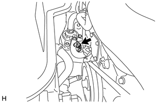
Check the connector connections and contact pressure of the relevant terminals for the inverter water pump assembly connector.
OK The connectors are connected securely and there are no contact pressure problems. Result Proceed to OK NG
NG
CONNECT SECURELY
OK
-
-
CHECK HARNESS AND CONNECTOR (POWER MANAGEMENT CONTROL ECU - INVERTER WATER PUMP ASSEMBLY)
-
Disconnect the A62 power management control ECU connector.
-
Disconnect the A12 inverter water pump assembly connector.
-
Measure the resistance according to the value(s) in the table below.
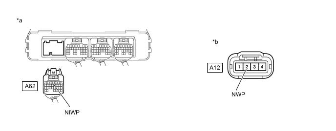
*a Rear view of wire harness connector
(to Power Management Control ECU)
*b Front view of wire harness connector
(to Inverter Water Pump Assembly)
Standard Resistance Tester Connection Condition Specified Condition A62-12 (NIWP) - A12-2 (NWP) Power switch off Below 1 Ω A62-12 (NIWP) or A12-2 (NWP) -Body ground and other terminals Power switch off 10 kΩ or higher -
Reconnect the A12 inverter water pump assembly connector.
-
Reconnect the A62 power management control ECU connector.
Result Proceed to OK NG
NG
REPAIR OR REPLACE HARNESS OR CONNECTOR
OK
-
-
CHECK POWER MANAGEMENT CONTROL ECU
-
Disconnect the A12 inverter water pump assembly connector.
-
Turn the power switch on (IG).
-
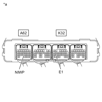
*a Component with harness connected
(Power Management Control ECU)
Measure the voltage according to the value(s) in the table below.
Standard Voltage Tester Connection Condition Specified Condition A62-12 (NIWP) - K32-6 (E1) Power switch on (IG) 11 to 14 V -
Turn the power switch off.
-
Reconnect the A12 inverter water pump assembly connector.
Result Proceed to OK NG
NG
REPLACE POWER MANAGEMENT CONTROL ECU Click here
OK
-
-
CLEAR DTC
Result Proceed to NEXT
-
Connect the GTS to the DLC3.
-
Turn the power switch on (IG).
-
Enter the following menus: Powertrain / Hybrid Control / Trouble Codes.
-
Read and record the DTCs and freeze frame data.
Powertrain > Hybrid Control > Trouble Codes -
Clear the DTCs and freeze frame data.
Powertrain > Hybrid Control > Clear DTCs -
Turn the power switch off.
Result Proceed to NEXT
NEXT
-
-
PERFORM ACTIVE TEST USING GTS (ACTIVATE THE WATER PUMP)
Note
Be sure to perform the inspection with the auxiliary battery voltage at 11 V or more.
Tech Tips
When the auxiliary battery voltage is low, the inverter water pump assembly may not operate.
-
Connect the GTS to the DLC3.
-
Turn the power switch on (IG).
-
Enter the following menus: Powertrain / Hybrid Control / Active Test / Activate the Water Pump.
Powertrain > Hybrid Control > Active TestTester Display Activate the Water Pump -
Perform the "Activate the Water Pump" Active Test.
-
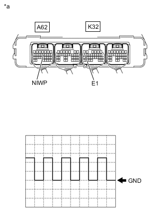
*a Component with harness connected
(Power Management Control ECU)
Connect an oscilloscope between the power management control ECU terminals specified in the table below, and measure the waveform.
Item Content Terminal A62-12 (NIWP) - K32-6 (E1) Equipment Setting 5 V/DIV., 100 ms./DIV. Condition Power switch on (IG), during Active Test OK The duration of wavelength A is 300 msec or less. -
Turn the power switch off.
Result Proceed to OK NG
OK
REPLACE POWER MANAGEMENT CONTROL ECU Click here
NG
REPLACE INVERTER WATER PUMP ASSEMBLY Click here
-
-
CHECK CONNECTOR CONNECTION CONDITION (INVERTER WATER PUMP ASSEMBLY CONNECTOR)
Result Proceed to OK NG
-
Check the connector connections and contact pressure of the relevant terminals for the inverter water pump assembly connector.
OK The connectors are connected securely and there are no contact pressure problems. Result Proceed to OK NG
NG
CONNECT SECURELY
OK
-
-
CHECK INSTALLATION CONDITION (INV W/PMP RELAY)
-
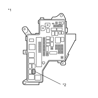
*1 No. 1 Engine Room Relay Block and No. 1 Junction Block Assembly *2 INV W/PMP Relay Check installation condition of the INV W/PMP relay.
OK INV W/PMP relay is installed correctly. Result Proceed to OK NG
NG
INSPECT RELAY (INV W/PMP) Click here
OK
-
-
CHECK HARNESS AND CONNECTOR (IGCT RELAY - INV W/PMP RELAY)
-
Remove the IGCT relay and INV W/PMP relay from the No. 1 engine room relay block and No. 1 junction block assembly.
-
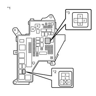
*1 No. 1 Engine Room Relay Block and No. 1 Junction Block Assembly *2 INV W/PMP Relay *3 IGCT Relay Measure the resistance according to the value(s) in the table below.
Standard Resistance Tester Connection Condition Specified Condition 5 (IGCT relay) - 1 (INV W/PMP relay) Power switch off Below 1 Ω Note
Do not apply excessive force when using the probes of the tester to perform the inspection. If excessive force is used, the holders will be damaged.
-
Install the IGCT relay and INV W/PMP relay.
Result Proceed to OK NG
NG
CHECK INSTALLATION CONDITION (IGCT NO. 4 FUSE) Click here
OK
-
-
INSPECT RELAY (INV W/PMP)
-
*1 No. 1 Engine Room Relay Block and No. 1 Junction Block Assembly *2 INV W/PMP Relay Remove the INV W/PMP relay from the No. 1 engine room relay block and No. 1 junction block assembly.
-
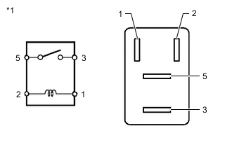
*1 INV W/PMP Relay Measure the resistance according to the value(s) in the table below.
Standard Resistance Tester Connection Condition Specified Condition 3 - 5 Auxiliary battery voltage is not applied between terminals 1 and 2 10 kΩ or higher Auxiliary battery voltage is applied between terminals 1 and 2 Below 1 Ω -
Install the INV W/PMP relay.
Result Proceed to OK NG
NG
CHECK RELAY HOLDER TERMINAL (INV W/PMP RELAY) Click here
OK
-
-
CHECK HARNESS AND CONNECTOR (INVERTER WATER PUMP ASSEMBLY - BODY GROUND)
-
Disconnect the A12 inverter water pump assembly connector.
-
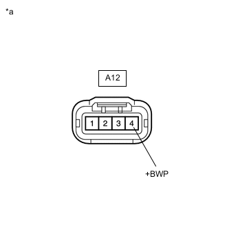
*a Front view of wire harness connector
(to Inverter Water Pump Assembly)
Measure the resistance according to the value(s) in the table below.
Standard Resistance Tester Connection Condition Specified Condition A12-4 (+BWP) - Body ground Power switch on (IG) 11 to 14 V Note
Turning the power switch on (IG) with the power management control ECU connector disconnected causes other DTCs to be stored. Clear the DTCs after performing this inspection.
-
Reconnect the A12 inverter water pump assembly connector.
Result Proceed to OK NG
NG
CHECK INSTALLATION CONDITION (INV W/PMP FUSE) Click here
OK
-
-
CHECK HARNESS AND CONNECTOR (INVERTER WATER PUMP ASSEMBLY - BODY GROUND)
-
Disconnect the A12 inverter water pump assembly connector.
-
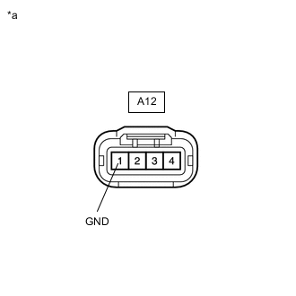
*a Front view of wire harness connector
(to Inverter Water Pump Assembly)
Measure the resistance according to the value(s) in the table below.
Standard Resistance Tester Connection Condition Specified Condition A12-1 (GND) - Body ground Power switch off Below 1 Ω -
Reconnect the A12 inverter water pump assembly connector.
Result Proceed to OK NG
OK
REPLACE INVERTER WATER PUMP ASSEMBLY Click here
NG
REPAIR OR REPLACE HARNESS OR CONNECTOR
-
-
CHECK INSTALLATION CONDITION (INV W/PMP FUSE)
-
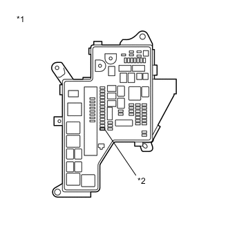
*1 No. 1 Engine Room Relay Block and No. 1 Junction Block Assembly *2 INV W/PMP Fuse Check installation condition of the INV W/PMP fuse.
OK INV W/PMP fuse is installed correctly. Result Proceed to OK NG
NG
CONNECT SECURELY
OK
-
-
INSPECT RELAY (INV W/PMP)
-
*1 No. 1 Engine Room Relay Block and No. 1 Junction Block Assembly *2 INV W/PMP Relay Remove the INV W/PMP relay from the No. 1 engine room relay block and No. 1 junction block assembly.
-
*1 INV W/PMP Relay Measure the resistance according to the value(s) in the table below.
Standard Resistance Tester Connection Condition Specified Condition 3 - 5 Auxiliary battery voltage is not applied between terminals 1 and 2 10 kΩ or higher Auxiliary battery voltage is applied between terminals 1 and 2 Below 1 Ω -
Install the INV W/PMP relay.
Result Proceed to OK NG
NG
CHECK RELAY HOLDER TERMINAL (INV W/PMP RELAY) Click here
OK
-
-
CHECK HARNESS AND CONNECTOR (INVERTER WATER PUMP ASSEMBLY - NO. 1 ENGINE ROOM RELAY BLOCK AND NO. 1 JUNCTION BLOCK ASSEMBLY)
-
Remove the INV W/PMP relay from the No. 1 engine room relay block and No. 1 junction block assembly.
-
Disconnect the A12 inverter water pump assembly connector.
-
Measure the resistance according to the value(s) in the table below.
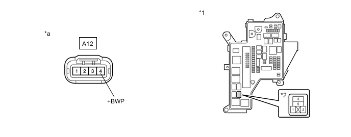
*1 No. 1 Engine Room Relay Block and No. 1 Junction Block Assembly *2 INV W/PMP Relay *a Front view of wire harness connector
(to Inverter Water Pump Assembly)
- - Standard Resistance Tester Connection Condition Specified Condition A12-4 (+BWP) - 3 (INV W/PMP relay) Power switch off Below 1 Ω A12-4 (+BWP) or 3 (INV W/PMP relay) - Body ground and other terminals Power switch off 10 kΩ or higher Note
Do not apply excessive force when using the probes of the tester to perform the inspection. If excessive force is used, the holders will be damaged.
-
Install the INV W/PMP relay.
-
Reconnect the A12 inverter water pump assembly connector.
Result Proceed to OK NG
NG
REPAIR OR REPLACE HARNESS OR CONNECTOR
OK
-
-
CHECK FUSE (INV W/PMP)
-
*1 No. 1 Engine Room Relay Block and No. 1 Junction Block Assembly *2 INV W/PMP Fuse Remove the INV W/PMP fuse from the No. 1 engine room relay block and No. 1 junction block assembly.
-
Measure the resistance according to the value(s) in the table below.
Standard Resistance Tester Connection Condition Specified Condition INV W/PMP fuse Always Below 1 Ω -
Install the INV W/PMP fuse.
Result Proceed to OK NG
OK
REPAIR OR REPLACE HARNESS OR CONNECTOR (INV W/PMP FUSE HOLDER TERMINAL OR INV W/PMP RELAY HOLDER TERMINAL)
NG
-
-
REPLACE INVERTER WATER PUMP ASSEMBLY
Result Proceed to NEXT
NEXT
REPLACE FUSE (INV W/PMP)
-
CHECK RELAY HOLDER TERMINAL (INV W/PMP RELAY)
-
Check the terminals of the INV W/PMP relay holder.
OK The terminals of the INV W/PMP relay holder are not bent, loose or corroded. Result Proceed to OK NG
NG
CHECK FUSE (IGCT NO. 4) Click here
OK
-
-
CHECK FUSE (IGCT NO. 4)
-
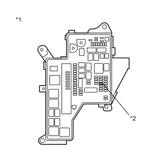
*1 No. 1 Engine Room Relay Block and No. 1 Junction Block Assembly *2 IGCT NO. 4 Fuse Remove the IGCT NO. 4 fuse from the No. 1 engine room relay block and No. 1 junction block assembly.
-
Measure the resistance according to the value(s) in the table below.
Standard Resistance Tester Connection Condition Specified Condition IGCT NO. 4 fuse Always Below 1 Ω -
Install the IGCT NO. 4 fuse.
Result Proceed to OK NG
OK
REPLACE RELAY (INV W/PMP)
NG
-
-
REPLACE RELAY (INV W/PMP)
Result Proceed to NEXT
NEXT
REPLACE FUSE (IGCT NO. 4)
-
CHECK RELAY HOLDER TERMINAL (INV W/PMP RELAY)
-
Check the terminals of the INV W/PMP relay holder.
OK The terminals of the INV W/PMP relay holder are not bent, loose or corroded. Result Proceed to OK NG
OK
REPLACE RELAY (INV W/PMP)
NG
REPAIR OR REPLACE HARNESS OR CONNECTOR (INV W/PMP RELAY HOLDER TERMINAL) Click here
-
-
CHECK FUSE (IGCT NO. 4)
-
*1 No. 1 Engine Room Relay Block and No. 1 Junction Block Assembly *2 IGCT NO. 4 Fuse Remove the IGCT NO. 4 fuse from the No. 1 engine room relay block and No. 1 junction block assembly.
-
Measure the resistance according to the value(s) in the table below.
Standard Resistance Tester Connection Condition Specified Condition IGCT NO. 4 fuse Always Below 1 Ω -
Install the IGCT NO. 4 fuse.
Result Proceed to OK NG
NG
REPAIR OR REPLACE HARNESS OR CONNECTOR (INV W/PMP RELAY HOLDER TERMINAL) Click here
OK
-
-
REPAIR OR REPLACE HARNESS OR CONNECTOR (INV W/PMP RELAY HOLDER TERMINAL)
Result Proceed to NEXT
NEXT
REPLACE RELAY (INV W/PMP)
-
REPAIR OR REPLACE HARNESS OR CONNECTOR (INV W/PMP RELAY HOLDER TERMINAL)
Result Proceed to NEXT
NEXT
REPLACE RELAY (INV W/PMP)
-
REPAIR OR REPLACE HARNESS OR CONNECTOR (INV W/PMP RELAY HOLDER TERMINAL)
Result Proceed to NEXT
NEXT
-
REPLACE FUSE (IGCT NO. 4)
Result Proceed to NEXT
NEXT
REPLACE RELAY (INV W/PMP)
-
CHECK INSTALLATION CONDITION (IGCT NO. 4 FUSE)
-
*1 No. 1 Engine Room Relay Block and No. 1 Junction Block Assembly *2 IGCT NO. 4 Fuse Check installation condition of the IGCT NO. 4 fuse.
OK IGCT NO. 4 fuse is installed correctly. Result Proceed to OK NG
NG
INSPECT RELAY (INV W/PMP) Click here
OK
-
-
CHECK FUSE (IGCT NO. 4)
-
*1 No. 1 Engine Room Relay Block and No. 1 Junction Block Assembly *2 IGCT NO. 4 Fuse Remove the IGCT NO. 4 fuse from the No. 1 engine room relay block and No. 1 junction block assembly.
-
Measure the resistance according to the value(s) in the table below.
Standard Resistance Tester Connection Condition Specified Condition IGCT NO. 4 fuse Always Below 1 Ω -
Install the IGCT NO. 4 fuse.
Result Proceed to OK NG
OK
REPAIR OR REPLACE HARNESS OR CONNECTOR (IGCT NO. 4 FUSE HOLDER TERMINAL)
NG
-
-
CHECK FUSE HOLDER TERMINAL (IGCT NO. 4 FUSE)
-
Check the terminals of the IGCT NO. 4 fuse holder.
OK The terminals of the IGCT NO. 4 fuse holder are not bent, loose or corroded. Result Proceed to OK NG
OK
REPLACE FUSE (IGCT NO. 4)
NG
-
-
REPAIR OR REPLACE HARNESS OR CONNECTOR (IGCT NO. 4 FUSE HOLDER TERMINAL)
Result Proceed to NEXT
NEXT
REPLACE FUSE (IGCT NO. 4)
-
INSPECT RELAY (INV W/PMP)
-
*1 No. 1 Engine Room Relay Block and No. 1 Junction Block Assembly *2 INV W/PMP Relay Remove the INV W/PMP relay from the No. 1 engine room relay block and No. 1 junction block assembly.
-
*1 INV W/PMP Relay Measure the resistance according to the value(s) in the table below.
Standard Resistance Tester Connection Condition Specified Condition 3 - 5 Auxiliary battery voltage is not applied between terminals 1 and 2 10 kΩ or higher Auxiliary battery voltage is applied between terminals 1 and 2 Below 1 Ω -
Install the INV W/PMP relay.
Result Proceed to OK NG
OK
CONNECT SECURELY (IGCT NO. 4 FUSE)
NG
REPLACE RELAY (INV W/PMP) Click here
-
-
INSPECT RELAY (INV W/PMP)
-
*1 No. 1 Engine Room Relay Block and No. 1 Junction Block Assembly *2 INV W/PMP Relay Remove the INV W/PMP relay from the No. 1 engine room relay block and No. 1 junction block assembly.
-
*1 INV W/PMP Relay Measure the resistance according to the value(s) in the table below.
Standard Resistance Tester Connection Condition Specified Condition 3 - 5 Auxiliary battery voltage is not applied between terminals 1 and 2 10 kΩ or higher Auxiliary battery voltage is applied between terminals 1 and 2 Below 1 Ω -
Install the INV W/PMP relay.
Result Proceed to OK NG
OK
CONNECT SECURELY (INV W/PMP RELAY)
NG
REPLACE RELAY (INV W/PMP)
-
-
REPLACE RELAY (INV W/PMP)
Result Proceed to NEXT
NEXT
CONNECT SECURELY (IGCT NO. 4 FUSE)