HYBRID CONTROL SYSTEM Pattern Select Switch Sport Mode Circuit
DESCRIPTION
When selecting SPORT*1 or SPORT S/S+*2 mode, the switch operation signal is sent to the ECM. Following this, the drive torque is optimally controlled to obtain a sporty feel in response to the driver's accelerator pedal operation.
-
*1: w/o Adaptive Variable Suspension System
-
*2: w/ Adaptive Variable Suspension System
WIRING DIAGRAM
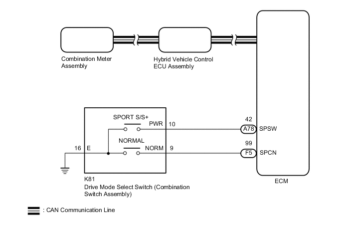
w/ Adaptive Variable Suspension System
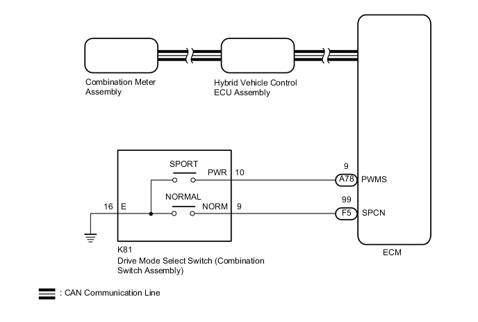
w/o Adaptive Variable Suspension System
PROCEDURE
-
READ VALUE USING GTS (CAN BUS CHECK)
Result Result Proceed to All of the ECUs and sensors that are currently connected to the CAN communication system are displayed. A None of the ECUs and sensors that are currently connected to the CAN communication system are displayed, or some of them are not displayed. B
-
Connect the GTS to the DLC3.
-
Turn the power switch on (IG).
-
Enter the following menus: System Select / CAN Bus Check.
CAN Bus CheckResult Result Proceed to All of the ECUs and sensors that are currently connected to the CAN communication system are displayed. A None of the ECUs and sensors that are currently connected to the CAN communication system are displayed, or some of them are not displayed. B -
Turn the power switch off.
B 
GO TO CAN COMMUNICATION SYSTEM Click here
A 
-
-
CHECK DTC OUTPUT (HEALTH CHECK)
Result Result Proceed to No DTCs are output. A DTCs are output. B
-
Connect the GTS to the DLC3.
-
Turn the power switch on (IG).
-
Enter the following menus: System Select / Health Check.
-
Check for DTCs.
Result Proceed to No DTCs are output. DTCs are output. -
Turn the power switch off.
B
GO TO DTC CHART
A
-
-
READ VALUE USING GTS (PATTERN SWITCH (PWR/M))
-
Connect the GTS to the DLC3.
-
Turn the power switch on (IG).
-
Enter the following menus: Powertrain / Hybrid Control / Data List / Pattern Switch (PWR/M).
Powertrain > Hybrid Control > Data ListTester Display Pattern Switch (PWR/M) -
Operate the drive mode select switch (combination switch assembly) to select SPORT*1 or SPORT S/S+*2 mode and read the value displayed on the GTS.
Powertrain > Hybrid Control > Data ListTester Display Measurement Item Range Normal Condition Pattern Switch (PWR/M) SPORT mode state ON or OFF In SPORT or SPORT S/S+ mode: ON
Not in SPORT or SPORT S/S+ mode: OFF
-
*1: w/o Adaptive Variable Suspension System
-
*2: w/ Adaptive Variable Suspension System
Result Result Proceed to The GTS display changes according to the drive mode select switch (combination switch assembly) operation. A The GTS display does not change according to the drive mode select switch (combination switch assembly) operation. B -
A
CHECK FOR INTERMITTENT PROBLEMS Click here
B
-
-
READ VALUE USING GTS (NORMAL MODE SWITCH, SPORT MODE SWITCH)
-
Connect the GTS to the DLC3.
-
Turn the power switch on (IG).
-
Enter the following menus: Powertrain / Engine and ECT / Data List / Normal Mode Switch and Sports Mode Switch.
Powertrain > Engine and ECT > Data ListTester Display Normal Mode Switch Sports Mode Switch -
Read the value displayed on the GTS.
Powertrain > Engine and ECT > Data ListTester Display Measurement Item Range Normal Condition Normal Mode Switch Normal mode switch status ON or OFF Drive mode select switch being pushed and held: ON
Drive mode select switch not operated: OFF
Sports Mode Switch SPORT mode switch status ON or OFF Drive mode select switch being turned and held at SPORT or SPORT S/S+ position: ON
Drive mode select switch not operated: OFF
Result Result Proceed to The GTS display changes according to the drive mode select switch (combination switch assembly) operation. A The GTS display does not change according to the drive mode select switch (combination switch assembly) operation. B
A
REPLACE ECM Click here
B
-
-
INSPECT DRIVE MODE SELECT SWITCH (COMBINATION SWITCH ASSEMBLY) (SPORT, SPORT S/S+, NORMAL, NORMAL CUSTOMIZE)
-
Remove the drive mode select switch (combination switch assembly).
-
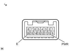
*a Component without harness connected
(Drive mode select switch (Combination Switch Assembly))
Check the drive mode select switch (combination switch assembly (SPORT or SPORT S/S+ switch)).
-
Measure the resistance according to the value(s) in the table below.
Standard Resistance Tester Connection Condition Specified Condition 10 (PWR) - 16 (E) Drive mode select switch (combination switch assembly) being turned and held at SPORT or SPORT S/S+ position Below 50 Ω Drive mode select switch (combination switch assembly) not operated 10 kΩ or higher
-
-
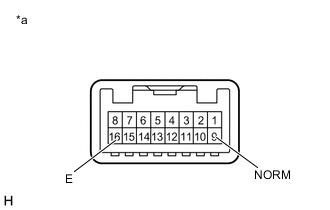
*a Component without harness connected
(Drive mode select switch (Combination Switch Assembly))
Check the drive mode select switch (combination switch assembly (NORMAL or NORMAL CUSTOMIZE switch)).
-
Measure the resistance according to the value(s) in the table below.
Standard Resistance Tester Connection Condition Specified Condition 9 (NORM) - 16 (E) Drive mode select switch (combination switch assembly) being pushed and held Below 50 Ω Drive mode select switch (combination switch assembly) not operated 10 kΩ or higher
-
-
Install the drive mode select switch (combination switch assembly).
Result Proceed to OK NG
NG
REPLACE DRIVE MODE SELECT SWITCH (COMBINATION SWITCH ASSEMBLY) Click here
OK
-
-
CHECK HARNESS AND CONNECTOR (DRIVE MODE SELECT SWITCH (COMBINATION SWITCH ASSEMBLY) - BODY GROUND)
-
Disconnect the K81 drive mode select switch (combination switch assembly) connector.
-
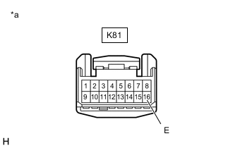
*a Front view of wire harness connector
(to Drive Mode Select Switch (Combination Switch Assembly))
Measure the resistance according to the value(s) in the table below.
Standard Resistance Tester Connection Condition Specified Condition K81-16 (E) - Body ground Always Below 1 Ω -
Reconnect the K81 drive mode select switch (combination switch assembly) connector.
Result Proceed to OK NG
NG
REPAIR OR REPLACE HARNESS OR CONNECTOR
OK
-
-
CHECK HARNESS AND CONNECTOR (AIR CONDITIONING AMPLIFIER ASSEMBLY - ECO MODE SWITCH (COMBINATION SWITCH ASSEMBLY))
-
Disconnect the A78 and F5 ECM connectors.
-
Disconnect the K81 drive mode select switch (combination switch assembly) connector.
-
Measure the resistance according to the value(s) in the table below.
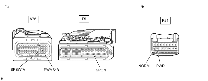
*A w/ Adaptive Variable Suspension System *B w/o Adaptive Variable Suspension System *a Front view of wire harness connector
(to ECM)
*b Front view of wire harness connector
(to Drive Mode Select Switch (Combination Switch Assembly))
Standard Resistance w/ Adaptive Variable Suspension System Tester Connection Condition Specified Condition A78-42 (SPSW) - K81-10 (PWR) Always Below 1 Ω A78-42 (SPSW) or K81-10 (PWR) - Body ground Always 10 kΩ or higher F5-99 (SPCN) - K81-9 (NORM) Always Below 1 Ω F5-99 (SPCN) or K81-9 (NORM) - Body ground Always 10 kΩ or higher w/o Adaptive Variable Suspension System Tester Connection Condition Specified Condition A78-9 (PWMS) - K81-10 (PWR) Always Below 1 Ω A78-9 (PWMS) or K81-10 (PWR) - Body ground Always 10 kΩ or higher F5-99 (SPCN) - K81-9 (NORM) Always Below 1 Ω F5-99 (SPCN) or K81-9 (NORM) - Body ground Always 10 kΩ or higher -
Reconnect the K81 drive mode select switch (combination switch assembly) connector.
-
Reconnect the A78 and F5 ECM connectors.
Result Proceed to OK NG
OK
REPLACE ECM Click here
NG
REPAIR OR REPLACE HARNESS OR CONNECTOR
-