HYBRID CONTROL SYSTEM Shift Paddle Switch Circuit
DESCRIPTION
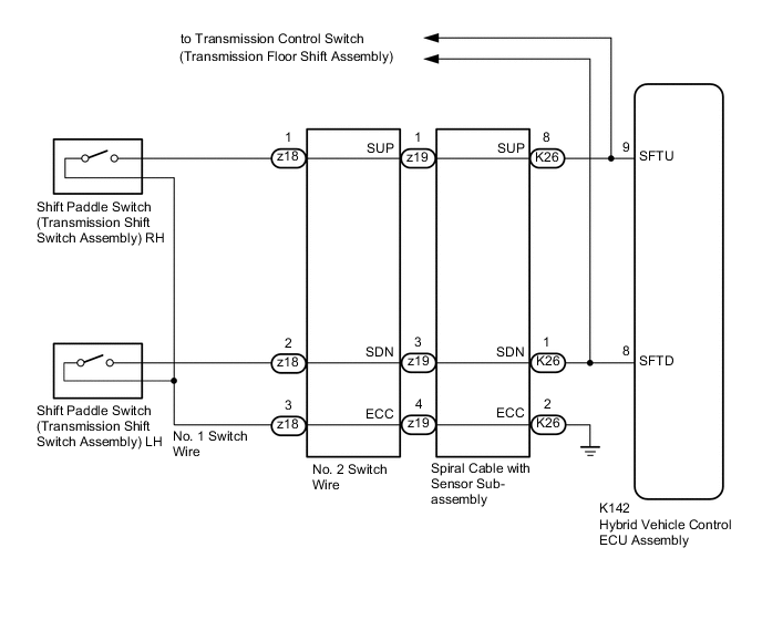
When the shift lever is in S, the shift range can be changed freely using the shift paddle switch of the transmission shift switch assembly.
WIRING DIAGRAM
Figure 1. w/ Dynamic Radar Cruise Control
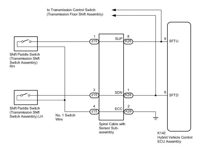
Figure 2. w/o Dynamic Radar Cruise Control
PROCEDURE
-
READ VALUE USING GTS (SPORT UP SHIFT SENS STATE, SPORT DWN SHIFT SENS STATE)
-
Connect the GTS to the DLC3.
-
Turn the power switch on (IG).
-
Enter the following menus: Powertrain / Hybrid Control / Data List / Sport Up Shift Sens State and Sport Dwn Shift Sens State.
Powertrain > Hybrid Control > Data ListTester Display Sport Up Shift Sens State Sport Dwn Shift Sens State -
Read the value displayed on the GTS.
Powertrain > Hybrid Control > Data ListTester Display Measurement Item Range Normal Condition Sport Up Shift Sens State "+" shift paddle switch ON or OFF "+" shift paddle switch RH operated: ON
"+" shift paddle switch RH not operated: OFF
Sport Dwn Shift Sens State "-" shift paddle switch ON or OFF "-" shift paddle switch LH operated: ON
"-" shift paddle switch LH not operated: OFF
Result Result Proceed to The GTS display changes according to the shift paddle switch (transmission shift switch assembly) operation. A The GTS display does not change according to the shift paddle switch (transmission shift switch assembly) operation. B
A 
CHECK FOR INTERMITTENT PROBLEMS Click here
B 
-
-
CHECK HARNESS AND CONNECTOR (SPIRAL CABLE WITH SENSOR SUB-ASSEMBLY - HYBRID VEHICLE CONTROL ECU ASSEMBLY)
-
Disconnect the K142 hybrid vehicle control ECU assembly connector.
-
Disconnect the K80 transmission control switch (transmission floor shift assembly) connector.
-
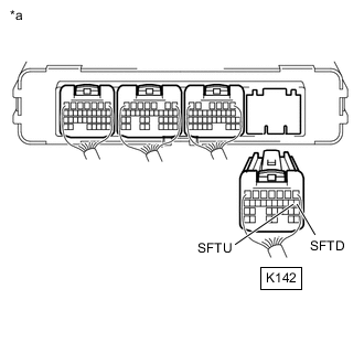
*a Rear view of wire harness connector
(to Hybrid Vehicle Control ECU Assembly)
Measure the resistance according to the value(s) in the table below.
Standard Resistance Tester Connection Condition Specified Condition K142-8 (SFTD) - Body ground Shift paddle switch LH (-) operated Below 2.5 Ω Shift paddle switch LH (-) not operated 1 MΩ or higher K142-9 (SFTU) - Body ground Shift paddle switch RH (+) operated Below 2.5 Ω Shift paddle switch RH (+) not operated 1 MΩ or higher -
Reconnect the K80 transmission control switch (transmission floor shift assembly) connector.
-
Reconnect the K142 hybrid vehicle control ECU assembly connector.
Result Proceed to OK NG
OK
REPLACE HYBRID VEHICLE CONTROL ECU ASSEMBLY Click here
NG
-
-
CHECK HARNESS AND CONNECTOR (SPIRAL CABLE WITH SENSOR SUB-ASSEMBLY - HYBRID VEHICLE CONTROL ECU ASSEMBLY)
-
Disconnect the K26 spiral cable with sensor sub-assembly connector.
-
Disconnect the K142 hybrid vehicle control ECU assembly connector.
-
Measure the resistance according to the value(s) in the table below.
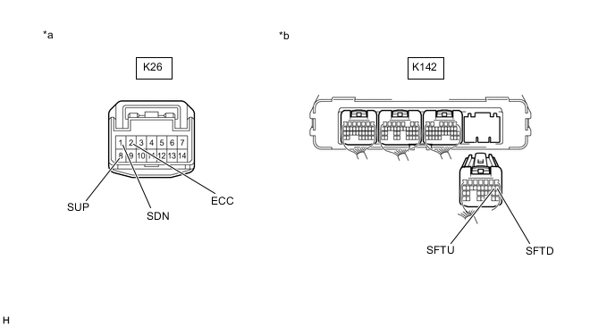
*a Front view of wire harness connector
(to Spiral Cable with Sensor Sub-assembly)
*b Rear view of wire harness connector
(to Hybrid Vehicle Control ECU Assembly)
Standard Resistance Tester Connection Condition Specified Condition K26-8 (SUP) - K142-9 (SFTU) Always Below 1 Ω K26-1 (SDN) - K142-8 (SFTD) Always Below 1 Ω K26-2 (ECC) - Body ground Always Below 1 Ω K26-8 (SUP) or K142-9 (SFTU) - Body ground Always 1 MΩ or higher K26-1 (SDN) or K142-8 (SFTD) - Body ground Always 1 MΩ or higher -
Reconnect the K142 hybrid vehicle control ECU assembly connector.
-
Reconnect the K26 spiral cable with sensor sub-assembly connector.
Result Proceed to OK NG
NG
REPAIR OR REPLACE HARNESS OR CONNECTOR
OK
-
-
INSPECT SPIRAL CABLE WITH SENSOR SUB-ASSEMBLY
-
Remove the spiral cable with sensor sub-assembly.
-
Set the spiral cable with sensor sub-assembly to the center position.
-
w/ Heated Steering System or Pre-collision System:
-
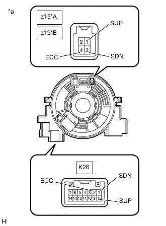
*A w/ Dynamic Radar Cruise Control *B w/o Dynamic Radar Cruise Control *a Component without harness connected
(Spiral Cable with Sensor Sub-assembly)
Measure the resistance between the terminals of the spiral cable with sensor sub-assembly according to the value(s) in the table below.
-
After setting the spiral cable with sensor sub-assembly to the center position, rotate the spiral cable with sensor sub-assembly 2.5 times clockwise and measure the resistance. Then rotate the spiral cable with sensor sub-assembly 2.5 times counterclockwise and measure the resistance.
-
After setting the spiral cable with sensor sub-assembly to the center position, rotate the spiral cable with sensor sub-assembly 2.5 times clockwise. Then while rotating the spiral cable with sensor sub-assembly 5 times counterclockwise, measure the resistance.
Standard Resistance w/ Dynamic Radar Cruise Control Tester Connection Condition Specified Condition z15-1 (SUP) - K26-8 (SUP) Always Below 3 Ω z15-3 (SDN) - K26-1 (SDN) Always Below 3 Ω z15-4 (ECC) - K26-2 (ECC) Always Below 3 Ω w/o Dynamic Radar Cruise Control Tester Connection Condition Specified Condition z19-1 (SUP) - K26-8 (SUP) Always Below 3 Ω z19-3 (SDN) - K26-1 (SDN) Always Below 3 Ω z19-4 (ECC) - K26-2 (ECC) Always Below 3 Ω Note
As the spiral cable with sensor sub-assembly may break, do not rotate the spiral cable with sensor sub-assembly more than the specified amount.
-
-
-
w/o Heated Steering System and Pre-collision System:
-
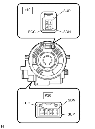
*a Component without harness connected
(Spiral Cable with Sensor Sub-assembly)
Measure the resistance between the terminals of the spiral cable with sensor sub-assembly according to the value(s) in the table below.
-
After setting the spiral cable with sensor sub-assembly to the center position, rotate the spiral cable with sensor sub-assembly 2.5 times clockwise and measure the resistance. Then rotate the spiral cable with sensor sub-assembly 2.5 times counterclockwise and measure the resistance.
-
After setting the spiral cable with sensor sub-assembly to the center position, rotate the spiral cable with sensor sub-assembly 2.5 times clockwise. Then while rotating the spiral cable with sensor sub-assembly 5 times counterclockwise, measure the resistance.
Standard Resistance Tester Connection Condition Specified Condition z19-1 (SUP) - K26-8 (SUP) Always Below 3 Ω z19-3 (SDN) - K26-1 (SDN) Always Below 3 Ω z19-4 (ECC) - K26-2 (ECC) Always Below 3 Ω Note
As the spiral cable with sensor sub-assembly may break, do not rotate the spiral cable with sensor sub-assembly more than the specified amount.
-
-
-
Install the spiral cable with sensor sub-assembly.
Result Proceed to OK NG
NG
REPLACE SPIRAL CABLE WITH SENSOR SUB-ASSEMBLY Click here
OK
-
-
INSPECT SHIFT PADDLE SWITCH (TRANSMISSION SHIFT SWITCH ASSEMBLY) LH
-
Remove the shift paddle switch (transmission shift switch assembly) LH.
-
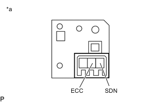
*a Component without harness connected
(Shift Paddle Switch (Transmission Shift Switch Assembly) LH)
Measure the resistance according to the value(s) in the table below.
Standard Resistance Tester Connection Condition Specified Condition SDN - ECC Shift paddle switch LH (-) operated Below 1 Ω SDN - ECC Shift paddle switch LH (-) not operated 10 kΩ or higher -
Install the shift paddle switch (transmission shift switch assembly) LH.
Result Proceed to OK NG
NG
REPLACE SHIFT PADDLE SWITCH (TRANSMISSION SHIFT SWITCH ASSEMBLY) LH Click here
OK
-
-
INSPECT SHIFT PADDLE SWITCH (TRANSMISSION SHIFT SWITCH ASSEMBLY) RH
-
Remove the shift paddle switch (transmission shift switch assembly) RH.
-
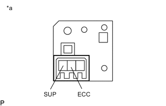
*a Component without harness connected
(Shift Paddle Switch (Transmission Shift Switch Assembly) RH)
Measure the resistance according to the value(s) in the table below.
Standard Resistance Tester Connection Condition Specified Condition SUP - ECC Shift paddle switch RH (+) operated Below 1 Ω SUP - ECC Shift paddle switch RH (+) not operated 10 kΩ or higher -
Install the shift paddle switch (transmission shift switch assembly) RH.
Result Proceed to OK NG
NG
REPLACE SHIFT PADDLE SWITCH (TRANSMISSION SHIFT SWITCH ASSEMBLY) RH Click here
OK
-
-
CHECK HARNESS AND CONNECTOR (SPIRAL CABLE WITH SENSOR SUB-ASSEMBLY - SHIFT PADDLE SWITCH (TRANSMISSION SHIFT SWITCH ASSEMBLY))
-
Disconnect the z15*1 No. 1 switch wire connector or z19*2 No. 2 switch wire connector.
-
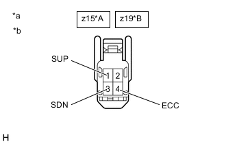
*A w/ Dynamic Radar Cruise Control *B w/o Dynamic Radar Cruise Control *a Component without harness connected
(No. 1 Switch Wire)
*b Component without harness connected
(No. 2 Switch Wire)
Measure the resistance according to the value(s) in the table below.
Standard Resistance Tester Connection Condition Specified Condition z15-3 (SDN) - z15-4 (ECC)*1
z19-3 (SDN) - z19-4 (ECC)*2
Shift paddle switch LH (-) operated Below 1 Ω Shift paddle switch LH (-) not operated 10 kΩ or higher z15-1 (SUP) - z15-4 (ECC)*1
z19-1 (SUP) - z19-4 (ECC)*2
Shift paddle switch RH (+) operated Below 1 Ω Shift paddle switch RH (+) not operated 10 kΩ or higher -
Reconnect the z15*1 No. 1 switch wire connector or z19*2 No. 2 switch wire connector.
*1: w/ Dynamic Radar Cruise Control
*2: w/o Dynamic Radar Cruise Control
Result Result Proceed to OK A NG
(w/ Dynamic Radar Cruise Control)
B NG
(w/o Dynamic Radar Cruise Control)
C
A
CHECK FOR INTERMITTENT PROBLEMS Click here
B
REPLACE NO. 1 SWITCH WIRE Click here
C
-
-
INSPECT NO. 1 SWITCH WIRE
-
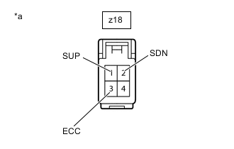
*a Component without harness connected
(No. 1 Switch Wire)
Disconnect the z18 No. 1 switch wire connector.
-
Measure the resistance according to the value(s) in the table below when the shift paddle switch (transmission shift switch assembly) is moved to each position.
Standard Resistance Tester Connection Condition Specified Condition z18-2 (SDN) - z18-3 (ECC) Shift paddle switch LH (-) operated Below 1 Ω Shift paddle switch LH (-) not operated 10 kΩ or higher z18-1 (SUP) - z18-3 (ECC) Shift paddle switch RH (+) operated Below 1 Ω Shift paddle switch RH (+) not operated 10 kΩ or higher -
Reconnect the z18 No. 1 switch wire connector.
Result Proceed to OK NG
OK
REPLACE NO. 2 SWITCH WIRE
NG
REPLACE NO. 1 SWITCH WIRE Click here
-