HYBRID CONTROL SYSTEM, Diagnostic DTC:P2532-772
| DTC Code | DTC Name |
|---|---|
| P2532-772 | Ignition Switch Run Position Circuit High |
DESCRIPTION
The power source and HV CPU processors and their functions are integrated into the power management control ECU. The power source CPU and HV CPU use CAN communication to communicate with each other inside the power management control ECU. The power source CPU controls the opening and closing of the IG2 relay. The HV CPU detects that the IG2 relay is stuck ON (closed) based on relay operation information received from the power source CPU via CAN communication.
Tech Tips
If DTC P2532-772 is stored, the vehicle will turn off.
| DTC No. | Detection Item | DTC Detection Condition | Trouble Area | MIL | Warning Indicate |
|---|---|---|---|---|---|
| P2532-772 | Ignition Switch Run Position Circuit High | Although the power management control ECU is sending a signal to open the IG2 relay, voltage is applied to the IG2 terminal. Although the power switch is turned off, the HV control system is not turned off. (1 trip detection logic) |
|
Does not come on | Master Warning Light: Comes on |
WIRING DIAGRAM
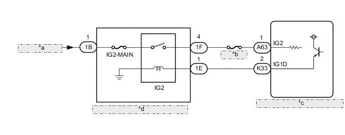
| *a | from Auxiliary Battery |
| *b | IGN NO. 1 |
| *c | Power Management Control ECU |
| *d | Semiconductor pwr integration ECU |
CAUTION / NOTICE / HINT
Tech Tips
After the repair, clear the DTCs and perform the following procedure to check that DTCs are not output.
-
Turn the power switch on (IG) and wait for 15 seconds or more.
-
Turn the power switch off and wait for 30 seconds or more.
PROCEDURE
-
CHECK HARNESS AND CONNECTOR (+B SHORT)
-
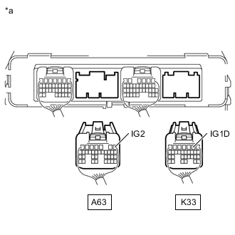
*a Rear view of wire harness connector
(to Power Management Control ECU)
Disconnect the A63 and K33 power management control ECU connector.
-
Measure the voltage according to the value(s) in the table below.
Standard Voltage Tester Connection Condition Specified Condition A63-1 (IG2) - Body ground Power switch off 1 V or less K33-2 (IG1D) - Body ground Power switch off 1 V or less -
Reconnect the A63 and K33 power management control ECU connector.
Result Proceed to OK NG
OK 
REPLACE POWER MANAGEMENT CONTROL ECU Click here
NG 
-
-
CHECK HARNESS AND CONNECTOR (POWER MANAGEMENT CONTROL ECU - SEMICONDUCTOR PWR INTEGRATION ECU)
-
Disconnect the A63 and K33 power management control ECU connector.
-
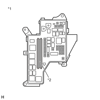
*1 No. 1 Engine Room Relay Block and No. 1 Junction Block Assembly *2 Semiconductor Pwr Integration ECU Remove the semiconductor pwr integration ECU from the No. 1 engine room relay block and No. 1 junction block assembly.
-
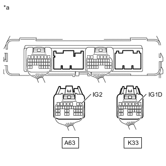
*a Rear view of wire harness connector
(to Power Management Control ECU)
Measure the voltage according to the value(s) in the table below.
Standard Voltage Tester Connection Condition Specified Condition A63-1 (IG2) - Body ground Power switch off 1 V or less K33-2 (IG1D) - Body ground Power switch off 1 V or less -
Install the semiconductor pwr integration ECU.
-
Reconnect the A63 and K33 power management control ECU connector.
Result Proceed to OK NG
OK
REPLACE SEMICONDUCTOR PWR INTEGRATION ECU Click here
NG
REPAIR OR REPLACE HARNESS OR CONNECTOR
-