HYBRID CONTROL SYSTEM, Diagnostic DTC:P0C73-776
| DTC Code | DTC Name |
|---|---|
| P0C73-776 | Motor Electronics Coolant Pump "A" Control Performance |
DESCRIPTION
The inverter water pump assembly transmits rotation revolution speed information to the power management control ECU. The power management control ECU monitors the revolution speed and detects malfunctions.
| DTC No. | Detection Item | DTC Detection Condition | Trouble Area | MIL | Warning Indicate |
|---|---|---|---|---|---|
| P0C73-776 | Motor Electronics Coolant Pump "A" Control Performance | The inverter water pump assembly revolution speed is abnormally high or low (or stop) for 1 minute or more or the inverter water pump assembly stops intermittently after abnormal revolution speed is detected. (1 trip detection logic) |
|
Comes on | Master Warning Light: Comes on |
Tech Tips
The inverter water pump assembly operates when the power switch is on (READY).
| DTC No. | ECU Data List |
|---|---|
| P0C73-776 |
|
*1: This Data List item is related to the inverter water pump assembly.
| DTC No. | Active Test |
|---|---|
| P0C73-776 | Activate the Water Pump*2 |
*2: This is an Active Test of the inverter water pump assembly.
WIRING DIAGRAM
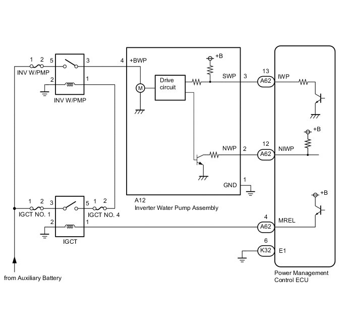
CAUTION / NOTICE / HINT
Note
If DTC P0A78-284, 286, P0A7A-322, 324, P0A94-553 or 557 is output, replace the inverter with converter assembly after this inspection.
Tech Tips
After the repair, clear the DTCs and perform the following procedure to check that DTCs are not output.
-
Turn the power switch on (READY) and wait for 2 minutes or more.
PROCEDURE
-
CHECK QUANTITY OF HV COOLANT
Result Result Proceed to No leaks are found and coolant level in the inverter reserve tank assembly is above the low line. A No leaks are found and coolant level in the inverter reserve tank assembly is below the low line. B HV coolant leaks are evident. C
-
Check the HV coolant level in the inverter reserve tank.
-
Check for HV coolant leaks.
Result Result Proceed to No leaks are found and coolant level in the inverter reserve tank assembly is above the low line. A No leaks are found and coolant level in the inverter reserve tank assembly is below the low line. B HV coolant leaks are evident. C Tech Tips
After repairing the HV coolant leaks and adding coolant, perform the "Activate the Water Pump" Active Test (HV Active Test item) and the "Control the Electric Cooling Fan" Active Test (Engine Active Test item) and make sure that there are no malfunctions.
B 
ADD HV COOLANT
C
If the result indicates that there are coolant leaks, the inverter water pump assembly is not malfunctioning. Do not replace the inverter water pump assembly.
A 
-
-
CHECK COOLANT HOSE
Result Proceed to OK NG
-
Check that the cooling system hoses are not kinked or clogged.
Result Proceed to OK NG
NG
REPAIR OR REPLACE COOLANT HOSE
OK
-
-
READ VALUE USING GTS (INVERTER W/P REVOLUTION)
Note
Be sure to perform the inspection with the auxiliary battery voltage at 11 V or more.
Tech Tips
-
When the auxiliary battery voltage is low, the inverter water pump assembly may not operate.
-
When the inverter water pump assembly signal line (SWP - IWP) is open or its connection is faulty, the inverter water pump assembly is operated forcibly.
-
Connect the GTS to the DLC3.
-
Turn the power switch on (IG).
-
Enter the following menus: Powertrain / Hybrid Control / Data List / Inverter W/P Revolution.
Powertrain > Hybrid Control > Data ListTester Display Inverter W/P Revolution -
Read the Data List.
Result Tester Display Condition Specified Condition Inverter W/P Revolution Power switch on (IG) 625 rpm or less Tech Tips
When the inverter water pump assembly is not operating, the Data List item "Inverter W/P Revolution" displays a value lower than 625 rpm.
-
Turn the power switch off.
Result Proceed to OK NG
NG 
CHECK CONNECTOR CONNECTION CONDITION (POWER MANAGEMENT CONTROL ECU CONNECTOR) Click here
OK
-
-
CLEAR DTC
Result Proceed to NEXT
-
Connect the GTS to the DLC3.
-
Turn the power switch on (IG).
-
Enter the following menus: Powertrain / Hybrid Control / Trouble Codes.
-
Read and record the DTCs and freeze frame data.
Powertrain > Hybrid Control > Trouble Codes -
Clear the DTCs and freeze frame data.
Powertrain > Hybrid Control > Clear DTCs -
Turn the power switch off.
Result Proceed to NEXT
NEXT
-
-
READ VALUE USING GTS (ACTIVATE THE WATER PUMP)
Note
Be sure to perform the inspection with the auxiliary battery voltage at 11 V or more.
Tech Tips
When the auxiliary battery voltage is low, the inverter water pump assembly may not operate.
-
Connect the GTS to the DLC3.
-
Turn the power switch on (IG).
-
Enter the following menus: Powertrain / Hybrid Control / Active Test / Activate the Water Pump.
Powertrain > Hybrid Control > Active TestTester Display Activate the Water Pump -
Select Inverter W/P Revolution in the Data List.
Powertrain > Hybrid Control > Data ListTester Display Inverter W/P Revolution -
While performing the "Activate the Water Pump" Active Test, check Inverter W/P Revolution in the Data List.
Result Tester Display Condition Specified Condition Inverter W/P Revolution Power switch on (IG) 2375 to 5750 rpm Tech Tips
-
Perform the Active Test with the inverter coolant temperature between -15 and 65°C (5 to 149°F).
-
When the inverter water pump assembly is not operating, the Data List item "Inverter W/P Revolution" displays a value lower than 625 rpm.
-
-
Turn the power switch off.
Result Proceed to OK NG
NG
GO TO STEP 7 Click here
OK
-
-
CHECK HV COOLANT (CHECK FOR CONDITIONS THAT MAY HAVE CAUSED FREEZING)
Result Result Proceed to Ambient Temperature value is above freezing temperature of the HV coolant. A Ambient Temperature value is below freezing temperature of the HV coolant. B
-
Connect the GTS to the DLC3.
-
Turn the power switch on (IG).
-
Enter the following menus: Powertrain / Hybrid Control / Trouble Codes.
-
Read the freeze frame data item Ambient Temperature using the GTS.
Powertrain > Hybrid Control > Trouble Codes -
Check if the freeze frame data item Ambient Temperature is below the freezing temperature of the HV coolant.
Result Result Proceed to Ambient Temperature value is above freezing temperature of the HV coolant. A Ambient Temperature value is below freezing temperature of the HV coolant. B Tech Tips
-
HV coolant (SLLC) with a 30% concentration freezes at -15 °C (5°F) and HV coolant (SLLC) with a 50% concentration freezes at -35°C (-31°F).
-
If the HV coolant freezes in the HV radiator or HV water pump, the coolant temperature in the inverter with converter assembly rises because the HV coolant cannot circulate. As a result, a DTC may be stored.
-
A DTC is stored when the water pump impeller cannot rotate due to freezing of the HV coolant.
-
If a DTC is stored due to freezing of HV coolant, the problem cannot be reproduced. Judge whether freezing of HV coolant occurred according to the freeze point of the HV coolant, HV coolant change history and ambient temperature when the DTC was stored.
-
-
Turn the power switch off.
A
REPLACE INVERTER WATER PUMP ASSEMBLY Click here
B
REPLACE HV COOLANT Click here
-
-
CHECK CONNECTOR CONNECTION CONDITION (POWER MANAGEMENT CONTROL ECU CONNECTOR)
Result Proceed to OK NG
-
Check the connector connections and contact pressure of the relevant terminals for the power management control ECU connectors.
OK The connectors are connected securely and there are no contact pressure problems. 
*A for LHD *B for RHD Result Proceed to OK NG
NG
CONNECT SECURELY
OK
-
-
CHECK CONNECTOR CONNECTION CONDITION (INVERTER WATER PUMP ASSEMBLY CONNECTOR)
-
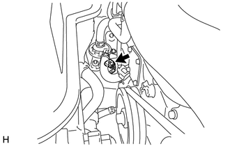
Check the connector connections and contact pressure of the relevant terminals for the inverter water pump assembly connector.
OK The connectors are connected securely and there are no contact pressure problems. Result Proceed to OK NG
NG
CONNECT SECURELY
OK
-
-
CHECK HARNESS AND CONNECTOR (POWER MANAGEMENT CONTROL ECU - INVERTER WATER PUMP ASSEMBLY)
-
Disconnect the A62 power management control ECU connector.
-
Disconnect the A12 inverter water pump assembly connector.
-
Measure the resistance according to the value(s) in the table below.
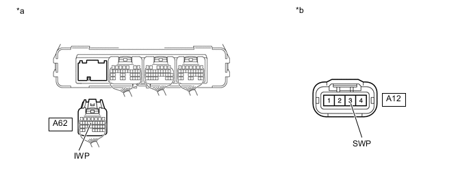
*a Rear view of wire harness connector
(to Power Management Control ECU)
*b Front view of wire harness connector
(to Inverter Water Pump Assembly)
Standard Resistance (Check for Open) Tester Connection Condition Specified Condition A62-13 (IWP) - A12-3 (SWP) Power switch off Below 1 Ω Standard Resistance (Check for Short) Tester Connection Condition Specified Condition A62-13 (IWP) or A12-3 (SWP) - Body ground and other terminals Power switch off 10 kΩ or higher -
Reconnect the A12 inverter water pump assembly connector.
-
Reconnect the A62 power management control ECU connector.
Result Proceed to OK NG
NG
REPAIR OR REPLACE HARNESS OR CONNECTOR
OK
-
-
READ VALUE USING GTS (INVERTER W/P REVOLUTION)
Note
Be sure to perform the inspection with the auxiliary battery voltage at 11 V or more.
Tech Tips
When the auxiliary battery voltage is low, the inverter water pump assembly may not operate.
-
Connect the GTS to the DLC3.
-
Disconnect the A12 inverter water pump assembly connector.
-
Turn the power switch on (IG).
-
Enter the following menus: Powertrain / Hybrid Control / Data List / Inverter W/P Revolution.
Powertrain > Hybrid Control > Data ListTester Display Inverter W/P Revolution -
Read the Data List.
Result Tester Display Condition Specified Condition Inverter W/P Revolution Power switch on (IG) 125 rpm or less -
Turn the power switch off.
-
Reconnect the A12 inverter water pump assembly connector.
Result Proceed to OK NG
NG
REPLACE POWER MANAGEMENT CONTROL ECU Click here
OK
-
-
CHECK HARNESS AND CONNECTOR (POWER MANAGEMENT CONTROL ECU - INVERTER WATER PUMP ASSEMBLY)
-
Disconnect the A62 power management control ECU connector.
-
Turn the power switch on (IG).
-
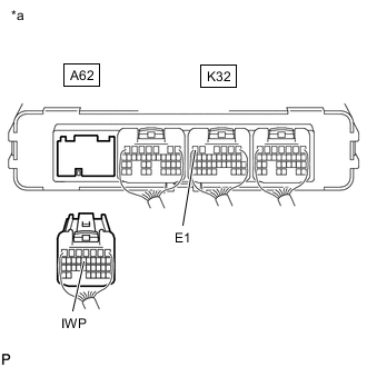
*a Rear view of wire harness connector
(to Power Management Control ECU)
Measure the voltage according to the value(s) in the table below.
Standard Voltage Tester Connection Condition Specified Condition A62-13 (IWP) - K32-6 (E1) Power switch on (IG) 11 to 14 V Note
Turning the power switch on (IG) with the power management control ECU connector disconnected causes other DTCs to be stored. Clear the DTCs after performing this inspection.
-
Turn the power switch off.
-
Reconnect the A62 power management control ECU connector.
Result Proceed to OK NG
NG
REPLACE INVERTER WATER PUMP ASSEMBLY Click here
OK
-
-
CHECK POWER MANAGEMENT CONTROL ECU (CHECK WAVEFORM)
-
Connect an oscilloscope between the power management control ECU terminals specified in the table below.
-
Turn the power switch on (IG).
-
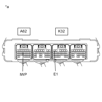
*a Component with harness connected
(Power Management Control ECU)
While turning the power switch on (IG), check the waveform between the power management control ECU terminals.
Item Content Terminal A62-13 (IWP) - K32-6 (E1) Equipment Setting 5 V/DIV., 50 ms./DIV. Condition Power switch on (IG) OK Waveform duty ratio is between 3% and 9%. -
Turn the power switch off.
Result Proceed to OK NG
OK
REPLACE INVERTER WATER PUMP ASSEMBLY Click here
NG
REPLACE POWER MANAGEMENT CONTROL ECU Click here
-