HYBRID CONTROL SYSTEM, Diagnostic DTC:P3107-214
| DTC Code | DTC Name |
|---|---|
| P3107-214 | Lost Communication with Airbag System Control Module |
DESCRIPTION
Refer to the description for DTC P3107-213.
| DTC No. | Detection Item | DTC Detection Condition | Trouble Area | MIL | Warning Indicate |
|---|---|---|---|---|---|
| P3107-214 | Lost Communication with Airbag System Control Module | Open or short to +B in the communication circuit (1 trip detection logic) |
|
Does not come on | Master Warning Light: Comes on |
| DTC No. | Data List |
|---|---|
| P3107-214 | Collision Signal (Airbag) |
WIRING DIAGRAM
Refer to the wiring diagram for DTC P0AE6-225.
Refer to the wiring diagram for DTC P3107-213.
CAUTION / NOTICE / HINT
Tech Tips
After the repair, clear the DTCs and perform the following procedure to check that DTCs are not output.
-
Turn the power switch on (IG) and wait for 15 seconds or more.
PROCEDURE
-
CHECK DTC OUTPUT (SRS AIRBAG)
-
Connect the GTS to the DLC3.
-
Turn the power switch on (IG).
-
Enter the following menus: Body Electrical / SRS Airbag / Trouble Codes.
-
Check for DTCs.
Body Electrical > SRS Airbag > Trouble CodesResult Proceed to Airbag system DTCs are not output. Airbag system DTCs are output. -
Turn the power switch off.
Airbag system DTCs are output. 
GO TO DTC CHART (AIRBAG SYSTEM) Click here
Airbag system DTCs are not output. 
-
-
CHECK AIRBAG SENSOR ASSEMBLY (CHECK WAVEFORM)
Result Proceed to The waveform appears as shown in the illustration. The waveform differs from the one shown in the illustration.
-
Connect an oscilloscope between the airbag sensor assembly terminals specified in the table below.
-
Turn the power switch on (READY).
-
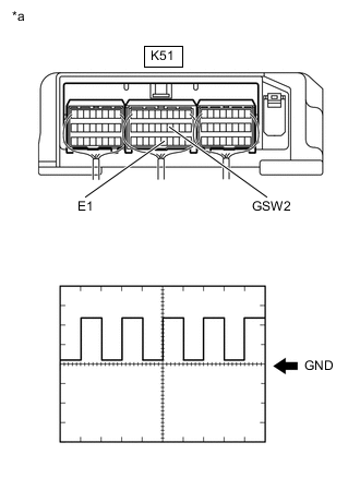
*a Component with harness connected
(Airbag Sensor Assembly)
Measure the waveform.
Item Contents Terminal K51-14 (GSW2) - K51-25 (E1) Equipment Setting 5 V/DIV., 500 ms./DIV. Condition Power switch on (READY) Result Proceed to The waveform appears as shown in the illustration. The waveform differs from the one shown in the illustration. -
Turn the power switch off.
The waveform differs from the one shown in the illustration. 
CHECK CONNECTOR CONNECTION CONDITION (POWER MANAGEMENT CONTROL ECU CONNECTOR) Click here
The waveform appears as shown in the illustration.
-
-
CLEAR DTC
Result Proceed to NEXT
-
Connect the GTS to the DLC3.
-
Turn the power switch on (IG).
-
Enter the following menus: Powertrain / Hybrid Control / Trouble Codes.
-
Read and record the DTCs and freeze frame data.
Powertrain > Hybrid Control > Trouble Codes -
Clear the DTCs and freeze frame data.
Powertrain > Hybrid Control > Clear DTCs -
Turn the power switch off.
Result Proceed to NEXT
NEXT
-
-
CHECK DTC OUTPUT (HYBRID CONTROL)
-
Connect the GTS to the DLC3.
-
Turn the power switch on (IG).
-
Enter the following menus: Powertrain / Hybrid Control / Trouble Codes.
-
Check for DTCs.
Powertrain > Hybrid Control > Trouble CodesResult Proceed to P3107-214 is not output. P3107-214 is output again. -
Turn the power switch off.
P3107-214 is output again.
REPLACE POWER MANAGEMENT CONTROL ECU Click here
P3107-214 is not output.
-
-
CHECK FOR INTERMITTENT PROBLEMS
Result Proceed to OK NG
OK
REPLACE POWER MANAGEMENT CONTROL ECU Click here
NG
REPAIR OR REPLACE MALFUNCTIONING PARTS, COMPONENT AND AREA
-
CHECK CONNECTOR CONNECTION CONDITION (POWER MANAGEMENT CONTROL ECU CONNECTOR)
Result Proceed to OK NG
-
Check the connector connections and contact pressure of the relevant terminals for the power management control ECU connectors.
OK The connectors are connected securely and there are no contact pressure problems. 
*A for LHD *B for RHD Result Proceed to OK NG
NG
CONNECT SECURELY
OK
-
-
CHECK CONNECTOR CONNECTION CONDITION (AIRBAG SENSOR ASSEMBLY CONNECTOR)
-

*a Component with harness connected
(Airbag Sensor Assembly)
Check the connector connections and contact pressure of the relevant terminals for the airbag sensor assembly connectors.
OK The connectors are connected securely and there are no contact pressure problems. Result Proceed to OK NG
NG
CONNECT SECURELY
OK
-
-
CHECK HARNESS AND CONNECTOR (+B SHORT)
-
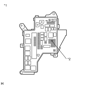
*1 No. 1 Engine Room Relay Block and No. 1 Junction Block Assembly *2 PM-IGCT Fuse Remove the PM-IGCT fuse from the No. 1 engine room relay block and No. 1 junction block assembly.
-
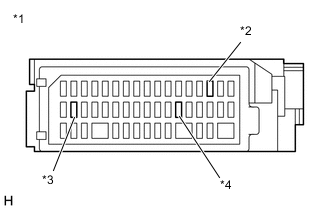
*1 Instrument Panel Junction Block Assembly *2 AM2 Fuse *3 IGN NO. 1 Fuse *4 ECU-ACC Fuse Remove the AM2 fuse, IGN No. 1 fuse and ECU-ACC fuse from the instrument panel junction block assembly.
-

*a Component without harness connected
(Airbag Sensor Assembly)
Disconnect the K51 airbag sensor assembly connector.
-
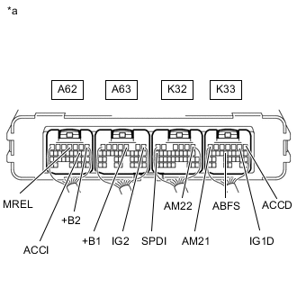
*a Component with harness connected
(Power Management Control ECU)
Measure the resistance according to the value(s) in the table below.
Standard Resistance Tester Connection Condition Specified Condition K33-13 (ABFS) - A62-1 (+B2) Power switch off 10 kΩ or higher K33-13 (ABFS) - A63-3 (+B1) Power switch off 10 kΩ or higher K33-13 (ABFS) - K32-1 (AM22) Power switch off 10 kΩ or higher K33-13 (ABFS) - K33-7 (AM21) Power switch off 10 kΩ or higher K33-13 (ABFS) - A62-4 (MREL) Power switch off 10 kΩ or higher K33-13 (ABFS) - A63-1 (IG2) Power switch off 10 kΩ or higher K33-13 (ABFS) - A62-10 (ACCI) Power switch off 10 kΩ or higher K33-13 (ABFS) - K33-1 (ACCD) Power switch off 10 kΩ or higher K33-13 (ABFS) - K33-2 (IG1D) Power switch off 10 kΩ or higher K33-13 (ABFS) - K32-16 (SPDI) Power switch off 10 kΩ or higher -
Reconnect the K51 airbag sensor assembly connector.
-
Install the AM2 fuse, IGN No. 1 fuse and ECU-ACC fuse.
-
Install the PM-IGCT fuse.
Result Proceed to OK NG
NG
CHECK HARNESS AND CONNECTOR (SHORT TO POWER SUPPLY WIRES) Click here
OK
-
-
CHECK HARNESS AND CONNECTOR (POWER MANAGEMENT CONTROL ECU - AIRBAG SENSOR ASSEMBLY)
-
Disconnect the K33 power management control ECU connector.
-
Disconnect the K51 airbag sensor assembly connector.
-
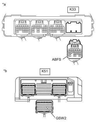
*a Rear view of wire harness connector
(to Power Management Control ECU)
*b Rear view of wire harness connector
(to Airbag Sensor Assembly)
Measure the resistance according to the value(s) in the table below.
Standard Resistance (Check for Open) Tester Connection Condition Specified Condition K33-13 (ABFS) - K51-14 (GSW2) Power switch off Below 1 Ω Standard Resistance (Check for Short) Tester Connection Condition Specified Condition K33-13 (ABFS) or K51-14 (GSW2) - Body ground and other terminals Power switch off 10 kΩ or higher Tech Tips
As necessary, check that there are no wires shorted to power supply when performing the above wire harness inspection.
-
Reconnect the K51 airbag sensor assembly connector.
-
Reconnect the K33 power management control ECU connector.
Result Proceed to OK NG
NG
REPAIR OR REPLACE HARNESS OR CONNECTOR
OK
-
-
CHECK POWER MANAGEMENT CONTROL ECU
-
*a Component without harness connected
(Airbag Sensor Assembly)
Disconnect the K51 airbag sensor assembly connector.
-
Turn the power switch on (IG).
-
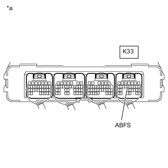
*a Component with harness connected
(Power Management Control ECU)
Measure the voltage according to the value(s) in the table below.
Standard Voltage Tester Connection Condition Specified Condition K33-13 (ABFS) - Body ground Power switch on (IG) 11 to 14 V Note
Turning the power switch on (IG) with the airbag sensor assembly connector disconnected causes other DTCs to be stored. Clear the DTCs after performing this inspection.
-
Turn the power switch off.
-
Reconnect the K51 airbag sensor assembly connector.
Result Proceed to OK NG
OK
REPLACE AIRBAG SENSOR ASSEMBLY Click here
NG
REPLACE POWER MANAGEMENT CONTROL ECU Click here
-
-
CHECK HARNESS AND CONNECTOR (SHORT TO POWER SUPPLY WIRES)
-
*1 No. 1 Engine Room Relay Block and No. 1 Junction Block Assembly *2 PM-IGCT Fuse Remove the PM-IGCT fuse from the No. 1 engine room relay block and No. 1 junction block assembly.
-
*1 Instrument Panel Junction Block Assembly *2 AM2 Fuse *3 IGN NO. 1 Fuse *4 ECU-ACC Fuse Remove the AM2 fuse, IGN No. 1 fuse and ECU-ACC fuse from the instrument panel junction block assembly.
-
*a Component without harness connected
(Airbag Sensor Assembly)
Disconnect the K51 airbag sensor assembly connector.
-
Disconnect the A62, A63, K32 and K33 power management control ECU connectors.
-
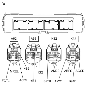
*a Rear view of wire harness connector
(to Power Management Control ECU)
Measure the resistance according to the value(s) in the table below.
Standard Resistance Tester Connection Condition Specified Condition K33-13 (ABFS) - A62-1 (+B2) Power switch off 10 kΩ or higher K33-13 (ABFS) - A63-3 (+B1) Power switch off 10 kΩ or higher K33-13 (ABFS) - K32-1 (AM22) Power switch off 10 kΩ or higher K33-13 (ABFS) - K33-7 (AM21) Power switch off 10 kΩ or higher K33-13 (ABFS) - A62-4 (MREL) Power switch off 10 kΩ or higher K33-13 (ABFS) - A63-1 (IG2) Power switch off 10 kΩ or higher K33-13 (ABFS) - A62-10 (ACCI) Power switch off 10 kΩ or higher K33-13 (ABFS) - K33-1 (ACCD) Power switch off 10 kΩ or higher K33-13 (ABFS) - K33-2 (IG1D) Power switch off 10 kΩ or higher K33-13 (ABFS) - K32-16 (SPDI) Power switch off 10 kΩ or higher -
Reconnect the A62, A63, K32 and K33 power management control ECU connectors.
-
Reconnect the K51 airbag sensor assembly connector.
-
Install the AM2 fuse, IGN No. 1 fuse and ECU-ACC fuse.
-
Install the PM-IGCT fuse.
Result Proceed to OK NG
OK
REPLACE POWER MANAGEMENT CONTROL ECU Click here
NG
REPAIR OR REPLACE HARNESS OR CONNECTOR
-