HYBRID CONTROL SYSTEM, Diagnostic DTC:P0A94-587
| DTC Code | DTC Name |
|---|---|
| P0A94-587 | DC / DC Converter Performance |
DESCRIPTION
For a description of the boost converter.
The MG ECU uses a voltage sensor (VL) that is built into the boost converter to detect the high voltage before it is boosted. The ECU also uses the battery voltage sensor to detect HV battery voltage (VB).
Tech Tips
Using the GTS, check the Data List values of "Power Resource VB" and "Batt Pack Current Val". If these values are not within the range below, there is a malfunction in the battery voltage sensor circuit.
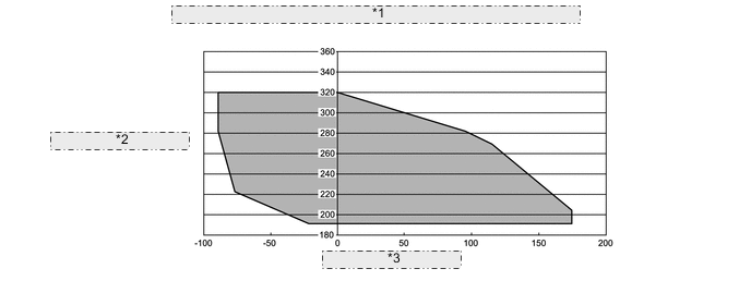
| *1 | HV Battery Voltage to HV Battery Current 20 to 40°C (68 to 104°F) |
| *2 | HV Battery Voltage (V) |
| *3 | HV Battery Current (A) |
| DTC No. | Detection Item | DTC Detection Condition | Trouble Area | MIL | Warning Indicate |
|---|---|---|---|---|---|
| P0A94-587 | DC / DC Converter Performance | Voltages from HV battery voltage (VB) sensor and boost converter voltage (VL) sensor deviate Difference between "VL-Voltage before Boosting" and "Power Resource VB" is large when the boosting request is given. (1 trip detection logic) |
|
Comes on | Master Warning Light: Comes on |
| DTC No. | Data List |
|---|---|
| P0A94-587 |
|
CAUTION / NOTICE / HINT
Tech Tips
When the accelerator pedal is not depressed with the power switch on (READY) and the shift lever in P, if "VL-Voltage before Boosting" and the "Power Resource VB" is approximately same after repair, the condition is judged as normal.
PROCEDURE
-
CHECK DTC OUTPUT (HYBRID CONTROL)
-
Connect the GTS to the DLC3.
-
Turn the power switch on (IG).
-
Enter the following menus: Powertrain / Hybrid Control / Trouble Codes.
-
Check for DTCs.
Powertrain > Hybrid Control > Trouble CodesResult Result Proceed to P0A94-587 only is output. Alternatively, P0A94-587 and any DTCs except P0AFC-129, P0A94-442 or P0A94-585 are output. A P0A94-587 and P0AFC-129 (HV battery voltage circuit malfunction) are output. B P0A94-587 and P0A94-442 (abnormal voltage execution value) are output. C P0A94-587 and P0A94-585 (boost converter voltage (VL) sensor performance problem) are output. D -
Turn the power switch off.
B 
GO TO DTC CHART (P0AFC-129) Click here
C
REPLACE INVERTER WITH CONVERTER ASSEMBLY Click here
D
GO TO DTC CHART (P0A94-585) Click here
A 
-
-
CLEAR DTC
Result Proceed to NEXT
-
Connect the GTS to the DLC3.
-
Turn the power switch on (IG).
-
Enter the following menus: Powertrain / Hybrid Control / Trouble Codes.
-
Read and record the DTCs and freeze frame data.
Powertrain > Hybrid Control > Trouble Codes -
Clear the DTCs and freeze frame data.
Powertrain > Hybrid Control > Clear DTCs -
Turn the power switch off.
Result Proceed to NEXT
NEXT
-
-
CHECK DTC OUTPUT (HYBRID CONTROL)
-
Connect the GTS to the DLC3. *1
-
Turn the power switch on (READY). *2
CAUTION:
Perform this road test only in an appropriate safe location, in accordance with all local laws.
-
Enter the following menus: Powertrain / Hybrid Control / Data List. *3
Powertrain > Hybrid Control > Data ListTester Display Power Resource VB VL-Voltage before Boosting Batt Pack Current Val -
If both "Power Resource VB" and "VL-Voltage before Boosting" are less than 258 V, move the shift lever to D and depress both the accelerator pedal and brake pedal at the same time to raise both values to 258 V or more. *4
-
Move the shift lever to P. *5
-
Set the air conditioning to MAX COOL and turn the headlights on. *6
-
Confirm that "Batt Pack Current Val" is more than 3 A. *7
-
Leave the vehicle for 15 seconds with the engine stopped during steps *5, *6 and *7. *8
-
Enter the following menus: Powertrain / Hybrid Control / Trouble codes. *9
-
Check for DTCs. *10
Powertrain > Hybrid Control > Trouble CodesNote
If the low HV battery charge warning light comes on, Move the shift lever to P and start the engine to charge the HV battery. After the engine stops, perform steps *1 through *10 again.
Result Result Proceed to No DTCs are output, or DTCs except the following are output. A P0AFC-129 (HV battery voltage circuit malfunction) is output. B P3004-132 (high voltage power supply line problem) is output. P0A94-585 (boost converter voltage (VL) sensor performance problem) is output. C P3000-388 (discharge inhibition) is output. D -
Turn the power switch off.
B
REPLACE BATTERY VOLTAGE SENSOR Click here
C
REPLACE INVERTER WITH CONVERTER ASSEMBLY Click here
D
LEAVE VEHICLE WITH THE SHIFT LEVER IN P, AND CHARGE HV BATTERY BY IDLING UNTIL IDLING STOPS (PERFORM STEPS *1 THROUGH *10)
A
-
-
CHECK DTC OUTPUT (HYBRID CONTROL)
-
Turn the power switch on (READY). *11
-
Perform a road test that repeats full acceleration to 60 km/h (37 mph) and then braking to a complete stop three times. *12
-
Connect the GTS to the DLC3. *13
-
Enter the following menus: Powertrain / Hybrid Control / Trouble Codes. *14
-
Check for DTCs. *15
Powertrain > Hybrid Control > Trouble CodesResult Result Proceed to No DTCs are output, or DTCs except the following are output. A P0AFC-129 (HV battery voltage circuit malfunction) is output. B P3004-132 (high voltage power supply line problem) is output. P0A94-585 (boost converter voltage (VL) sensor performance problem) is output. C P3000-388 (discharge inhibition) is output. D -
Turn the power switch off.
B
REPLACE BATTERY VOLTAGE SENSOR Click here
C
REPLACE INVERTER WITH CONVERTER ASSEMBLY Click here
D
LEAVE VEHICLE WITH THE SHIFT LEVER IN P, AND CHARGE HV BATTERY BY IDLING UNTIL IDLING STOPS (PERFORM STEPS *11 THROUGH *15)
A
-
-
READ VALUE USING GTS
-
Connect the GTS to the DLC3.
-
Turn the power switch on (READY).
-
Enter the following menus: Powertrain / Hybrid Control / Data List / Power Resource VB, VL-Voltage before Boosting, VH-Voltage after Boosting.
Powertrain > Hybrid Control > Data ListTester Display Power Resource VB VL-Voltage before Boosting VH-Voltage after Boosting -
If both "Power Resource VB" and "VL-Voltage before Boosting" are less than 258 V, move the shift lever to D and depress both the accelerator pedal and brake pedal at the same time to raise both values to 258 V or more.
-
Turn the engine off, move the shift lever to P, and read the Data List with the vehicle stationary.
Result Result Proceed to Both of the following are not satisfied. A Both of the following are satisfied:
-
Difference between "Power Resource VB" and "VH-Voltage after Boosting" is less than 5 V.
-
Difference between "VL-Voltage before Boosting" and "VH-Voltage after Boosting" is more than 30 V.
B Both of the following are satisfied:
-
Difference between "VH-Voltage after Boosting" and "VL-Voltage before Boosting" is less than 5 V.
-
Difference between "Power Resource VB" and "VH-Voltage after Boosting" is more than 15 V.
C -
-
Turn the power switch off.
B
REPLACE INVERTER WITH CONVERTER ASSEMBLY Click here
C
REPLACE BATTERY VOLTAGE SENSOR Click here
A
-
-
CHECK FREEZE FRAME DATA (HYBRID CONTROL)
-
Connect the GTS to the DLC3.
-
Turn the power switch on (IG).
-
Enter the following menus: Powertrain / Hybrid Control / Trouble Codes.
-
Read the freeze frame data of DTC P0A94-587.
Result Result Proceed to Both of the following are satisfied or both of the following are not satisfied. A "Power Resource VB" is less than 192 V or more than 320 V. B "VL-Voltage before Boosting" is less than 192 V or more than 320 V. C -
Turn the power switch off.
B
REPLACE BATTERY VOLTAGE SENSOR Click here
C
REPLACE INVERTER WITH CONVERTER ASSEMBLY Click here
A
-
-
CHECK FREEZE FRAME DATA (HYBRID CONTROL)
-
Connect the GTS to the DLC3.
-
Turn the power switch on (IG).
-
Enter the following menus: Powertrain / Hybrid Control / Trouble Codes.
-
Read the freeze frame data of DTC P0A94-587.
Tech Tips
In the freeze frame data, read the "Power Resource VB" and all of the "Battery Block Vol".
Result Result Proceed to Freeze frame data is not stored. A Both of the following are satisfied:
-
Sum of all "Battery Block Vol" is more than ("Power Resource VB" -45 V)
-
Sum of all "Battery Block Vol" is less than ("Power Resource VB" +30 V)
B Neither A nor B is satisfied. C -
-
Turn the power switch off.
B
REPLACE INVERTER WITH CONVERTER ASSEMBLY Click here
C
REPLACE BATTERY VOLTAGE SENSOR Click here
A
-
-
READ VALUE USING GTS (DATA LIST)
-
Connect the GTS to the DLC3.
-
Turn the power switch on (READY).
-
Enter the following menus: Powertrain / Hybrid Control / Data List.
-
If both "Power Resource VB" and "VL-Voltage before Boosting" are less than 258 V, move the shift lever to D and depress both the accelerator pedal and brake pedal at the same time to raise both values to 258 V or more.
Powertrain > Hybrid Control > Data ListTester Display Power Resource VB VL-Voltage before Boosting -
Turn the engine off, push the P position switch, and read the "Power Resource VB" and all of the "Battery Block Vol", with the vehicle is stationary.
Powertrain > Hybrid Control > Data ListTester Display Battery Block Vol -V01 Battery Block Vol -V02 Battery Block Vol -V03 Battery Block Vol -V04 Battery Block Vol -V05 Battery Block Vol -V06 Battery Block Vol -V07 Battery Block Vol -V08 Battery Block Vol -V09 Battery Block Vol -V10 Battery Block Vol -V11 Battery Block Vol -V12 Battery Block Vol -V13 Battery Block Vol -V14 Battery Block Vol -V15 Battery Block Vol -V16 Power Resource VB Result Result Proceed to Both of the following are satisfied:
-
Sum of all "Battery Block Vol" is more than ("Power Resource VB" -45 V)
-
Sum of all "Battery Block Vol" is less than ("Power Resource VB" +30 V)
A The preceding condition is not satisfied. B -
-
Turn the power switch off.
A
REPLACE INVERTER WITH CONVERTER ASSEMBLY Click here
B
REPLACE BATTERY VOLTAGE SENSOR Click here
-