HYBRID CONTROL SYSTEM, Diagnostic DTC:P0A7A-517, P0A7A-809
| DTC Code | DTC Name |
|---|---|
| P0A7A-517 | Generator Inverter Performance |
| P0A7A-809 | Generator Inverter Performance |
DESCRIPTION
For a description of the inverter.
If a circuit malfunction, overheating or an internal short circuit of the generator inverter is detected, a signal is sent from the inverter with converter assembly to the MG ECU via the inverter fail signal line.
If an abnormal amount of current flows through the generator inverter, the MG ECU detects it and sends a signal to inform the power management control ECU of the malfunction.
| DTC No. | Detection Item | DTC Detection Condition | Trouble Area | MIL | Warning Indicate |
|---|---|---|---|---|---|
| P0A7A-517 | Generator Inverter Performance | Generator inverter fail signal detection (MG ECU malfunction) Overcurrent occurs in the generator inverter*. (1 trip detection logic) |
Inverter with converter assembly | Comes on | Master Warning Light: Comes on |
| P0A7A-809 | Generator Inverter Performance | Abnormal generator inverter current (overcurrent) detection (MG ECU malfunction) (1 trip detection logic) |
Inverter with converter assembly | Comes on | Master Warning Light: Comes on |
*: The MG ECU, which is built into in the inverter with converter assembly, can be suspected as a main cause of the malfunction.
CAUTION / NOTICE / HINT
CAUTION:
-
Before inspecting the high-voltage system or disconnecting the low voltage connector of the inverter with converter assembly, take safety precautions such as wearing insulated gloves and removing the service plug grip to prevent electrical shocks. After removing the service plug grip, put it in your pocket to prevent other technicians from accidentally reconnecting it while you are working on the high-voltage system.
-
After removing the service plug grip, wait for at least 10 minutes before touching any of the high-voltage connectors or terminals. After waiting for 10 minutes, check the voltage at the terminals in the inspection point in the inverter with converter assembly. The voltage should be 0 V before beginning work.
Tech Tips
Waiting for at least 10 minutes is required to discharge the high-voltage capacitor inside the inverter with converter assembly.
Note
After turning the power switch off, waiting time may be required before disconnecting the cable from the negative (-) auxiliary battery terminal. Therefore, make sure to read the disconnecting the cable from the negative (-) auxiliary battery terminal notices before proceeding with work.
Tech Tips
After the repair, clear the DTCs and perform the following procedure to check that DTCs are not output.
-
Turn the power switch on (READY) and wait for 5 seconds or more.
-
Drive the vehicle for approximately 10 minutes mainly using the engine.
PROCEDURE
-
CHECK DTC OUTPUT (HYBRID CONTROL)
-
Connect the GTS to the DLC3.
-
Turn the power switch on (IG).
-
Enter the following menus: Powertrain / Hybrid Control / Trouble Codes.
-
Check for DTCs.
Powertrain > Hybrid Control > Trouble CodesResult Proceed to P0A7A-203 is not output. P0A7A-203 is also output. Note
-
If P0A7A-203 is output, troubleshoot it first. After completing the troubleshooting for P0A7A-203, perform troubleshooting for this DTC.
-
Parts repaired or replaced during troubleshooting for P0A7A-203 do not need to be re-inspected in this diagnosis procedure.
-
-
Turn the power switch off.
P0A7A-203 is also output. 
GO TO DTC CHART (P0A7A-203) Click here
P0A7A-203 is not output. 
-
-
CHECK DTC OUTPUT (HYBRID CONTROL)
-
Connect the GTS to the DLC3.
-
Turn the power switch on (IG).
-
Enter the following menus: Powertrain / Hybrid Control / Trouble Codes.
-
Check for DTCs.
Powertrain > Hybrid Control > Trouble CodesTech Tips
-
If P0A7A-203 was not output in step 1 of this diagnosis procedure, check Table 1 below.
-
If P0A7A-203 was output in step 1 of this diagnosis procedure, diagnose that DTC first, then check Table 2 below.
Result Result Proceed to P0A7A-517 or 809 only is output, or DTCs except the ones in the tables below are also output. A Any of the following DTCs are also output. B Table 1 Relevant DTC P0A1A (all INF codes)*1 Generator Control Module P0A1B (all INF codes)*1 Drive Motor "A" Control Module P0A1D (all INF codes)*1 Hybrid Powertrain Control Module P0A3F-243 Drive Motor "A" Position Sensor Circuit P0A40-500 Drive Motor "A" Position Sensor Circuit Range/Performance P0A41-245 Drive Motor "A" Position Sensor Circuit Low P0A4B-253 Generator Position Sensor Circuit P0A4C-513 Generator Position Sensor Circuit Range/Performance P0A4D-255 Generator Position Sensor Circuit Low P0A60 (all INF codes)*1 Drive Motor "A" Phase V Current P0A63 (all INF codes)*1 Drive Motor "A" Phase W Current P0A72 (all INF codes)*1 Generator Phase V Current P0A75 (all INF codes)*1 Generator Phase W Current P0A78-266, 267, 586 Drive Motor "A" Inverter Performance P0A94-585, 587, 589, 590 DC / DC Converter Performance P0C76-523 Hybrid Battery System Discharge Time Too Long Table 2 Relevant DTC P0A1A (all INF codes)*1 Generator Control Module P0A1B (all INF codes)*1 Drive Motor "A" Control Module P0A1D (all INF codes)*1 Hybrid Powertrain Control Module P0A3F-243 Drive Motor "A" Position Sensor Circuit P0A40-500 Drive Motor "A" Position Sensor Circuit Range/Performance P0A41-245 Drive Motor "A" Position Sensor Circuit Low P0A4B-253 Generator Position Sensor Circuit P0A4C-513 Generator Position Sensor Circuit Range/Performance P0A4D-255 Generator Position Sensor Circuit Low P0A60 (all INF codes)*1 Drive Motor "A" Phase V Current P0A63 (all INF codes)*1 Drive Motor "A" Phase W Current P0A72-333 Generator Phase V Current P0A75-341 Generator Phase W Current P0A78-266, 267, 586 Drive Motor "A" Inverter Performance P0A94-585, 587, 589, 590 DC / DC Converter Performance P0C76-523 Hybrid Battery System Discharge Time Too Long Tech Tips
-
*1: If any INF codes are output for this DTC, refer to the corresponding diagnostic procedure.
-
P0A7A-517 or P0A7A-809 may be stored due to a malfunction which also causes DTCs in the preceding tables to be stored. In this case, first troubleshoot the output DTCs in the preceding tables. Then, perform a test to attempt to reproduce the problems, and check that no DTCs are output.
-
-
Turn the power switch off.
B
GO TO DTC CHART (HYBRID CONTROL SYSTEM) Click here
A
-
-
CHECK CONNECTOR CONNECTION CONDITION (INVERTER WITH CONVERTER ASSEMBLY CONNECTOR)
Result Result Proceed to OK A NG (The connector is not connected securely.) B NG (The terminals are not making secure contact or are deformed, or water or foreign matter exists in the connector.) C CAUTION:
Be sure to wear insulated gloves.
-
Check that the service plug grip is not installed.
Note
After removing the service plug grip, do not turn the power switch on (READY), unless instructed by the repair manual because this may cause a malfunction.
-
Check connection condition of the low voltage connector of the inverter with converter assembly and the contact pressure of each terminal. Check the terminals for deformation, and check the connector for water ingress and foreign matter.
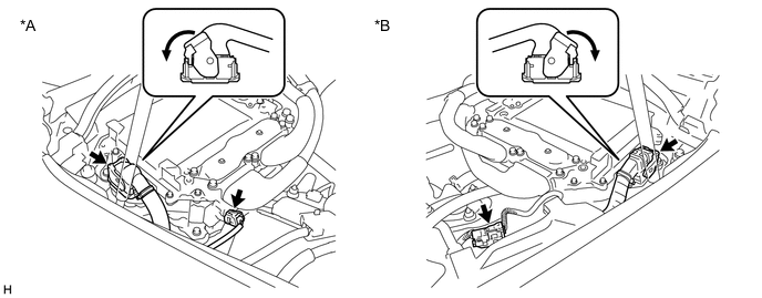
*A for LHD *B for RHD Note
Before disconnecting the connector, confirm that it is properly connected by checking that the locking claws are engaged and that the connector does not pull out.
OK - The connector is connected securely. - The terminals are not deformed and are connected securely. - No water or foreign matter in the connector. Result Result Proceed to OK A NG (The connector is not connected securely.) B NG (The terminals are not making secure contact or are deformed, or water or foreign matter exists in the connector.) C Tech Tips
When connecting the connector, insert it with the locking lever in the raised position. Rotate the lever downward and make sure that the connector is pulled into its socket. When the locking lever is in its fully closed position, a click will be heard as its locking claws engage. After the click is heard, pull up on the connector to confirm that it is properly connected.
A
REPLACE INVERTER WITH CONVERTER ASSEMBLY Click here
B
CONNECT SECURELY
C
REPAIR OR REPLACE HARNESS OR CONNECTOR
-