HYBRID CONTROL SYSTEM, Diagnostic DTC:P0ADF-229
| DTC Code | DTC Name |
|---|---|
| P0ADF-229 | Hybrid Battery Negative Contactor Control Circuit Low |
DESCRIPTION
Refer to the description for DTC P0AE6-225.
| DTC No. | Detection Item | DTC Detection Condition | Trouble Area | MIL | Warning Indicate |
|---|---|---|---|---|---|
| P0ADF-229 | Hybrid Battery Negative Contactor Control Circuit Low | Short to GND in the SMRG circuit Primary circuit of SMR (-) is malfunctioning. (2 trip detection logic) |
|
Does not come on | Master Warning Light: Comes on |
| DTC No. | Data List |
|---|---|
| P0ADF-229 |
|
CAUTION / NOTICE / HINT
CAUTION:
-
Before inspecting the high-voltage system or disconnecting the low voltage connector of the inverter with converter assembly, take safety precautions such as wearing insulated gloves and removing the service plug grip to prevent electrical shocks. After removing the service plug grip, put it in your pocket to prevent other technicians from accidentally reconnecting it while you are working on the high-voltage system.
-
After removing the service plug grip, wait for at least 10 minutes before touching any of the high-voltage connectors or terminals. After waiting for 10 minutes, check the voltage at the terminals in the inspection point in the inverter with converter assembly. The voltage should be 0 V before beginning work.
Tech Tips
Waiting for at least 10 minutes is required to discharge the high-voltage capacitor inside the inverter with converter assembly.
Note
After turning the power switch off, waiting time may be required before disconnecting the cable from the negative (-) auxiliary battery terminal. Therefore, make sure to read the disconnecting the cable from the negative (-) auxiliary battery terminal notices before proceeding with work.
Tech Tips
-
If DTC P0ADF-229 is output, the power switch cannot be turned on (READY).
-
After the repair, clear the DTCs, perform the following procedure and check that the same DTC (including pending DTC) is not output.
-
Turn the power switch off and wait for 30 seconds or more.
-
Turn the power switch on (READY) and wait for 30 seconds or more.
-
Turn the power switch off and wait for 60 seconds or more.
PROCEDURE
-
CHECK HARNESS AND CONNECTOR (HYBRID VEHICLE CONTROL ECU ASSEMBLY - BODY GROUND)
-
Disconnect the K141 hybrid vehicle control ECU assembly connector.
-
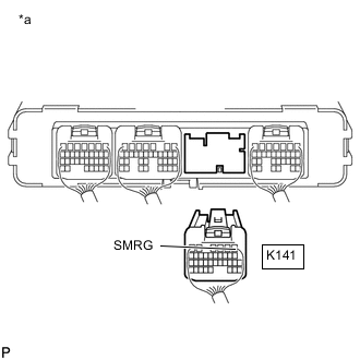
*a Rear view of wire harness connector
(to Hybrid Vehicle Control ECU Assembly)
Measure the resistance according to the value(s) in the table below.
Standard Resistance Tester Connection Condition Specified Condition K141-1 (SMRG) - Body ground Power switch off 25.0 to 59.0 Ω -
Reconnect the K141 hybrid vehicle control ECU assembly connector.
Result Proceed to OK NG
OK 
REPLACE HYBRID VEHICLE CONTROL ECU ASSEMBLY Click here
NG 
-
-
CHECK HARNESS AND CONNECTOR (HYBRID VEHICLE CONTROL ECU ASSEMBLY - HYBRID BATTERY JUNCTION BLOCK ASSEMBLY)
CAUTION:
Be sure to wear insulated gloves.
-
Check that the service plug grip is not installed.
Note
After removing the service plug grip, do not turn the power switch on (READY), unless instructed by the repair manual because this may cause a malfunction.
-
Remove the upper hybrid battery cover sub-assembly.
-
Disconnect the k2 hybrid battery junction block assembly connector.
-
Disconnect the K141 hybrid vehicle control ECU assembly connector.
-
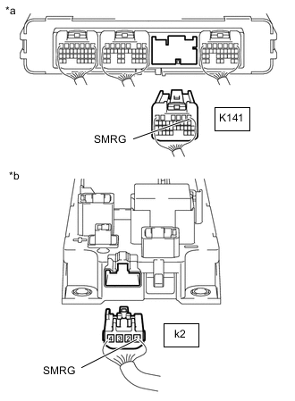
*a Rear view of wire harness connector
(to Hybrid Vehicle Control ECU Assembly)
*b Rear view of wire harness connector
(to Hybrid Battery Junction Block Assembly)
Measure the resistance according to the value(s) in the table below.
Standard Resistance Tester Connection Condition Specified Condition K141-1 (SMRG) or k2-1 (SMRG) - Body ground and other terminals Power switch off 10 kΩ or higher -
Reconnect the K141 hybrid vehicle control ECU assembly connector.
-
Reconnect the k2 hybrid battery junction block assembly connector.
-
Install the upper hybrid battery cover sub-assembly.
Result Proceed to OK NG
OK
REPLACE HV BATTERY JUNCTION BLOCK ASSEMBLY Click here
NG
REPAIR OR REPLACE HARNESS OR CONNECTOR
-