HYBRID CONTROL SYSTEM, Diagnostic DTC:P0A38-257, P0A39-259
| DTC Code | DTC Name |
|---|---|
| P0A38-257 | Generator Temperature Sensor Circuit Low |
| P0A39-259 | Generator Temperature Sensor Circuit High |
DESCRIPTION
Refer to the description for DTC P0A37-260.
| DTC No. | Detection Item | DTC Detection Condition | Trouble Area | MIL | Warning Indicate |
|---|---|---|---|---|---|
| P0A38-257 | Generator Temperature Sensor Circuit Low | Short to GND in the generator temperature sensor circuit (1 trip detection logic) |
|
Does not come on | Master Warning Light: Comes on |
| P0A39-259 | Generator Temperature Sensor Circuit High | Open or short to +B in the generator temperature sensor circuit (1 trip detection logic) |
|
Does not come on | Master Warning Light: Comes on |
Tech Tips
After confirming that DTC P0A38-257 or P0A39-259 is output, use the GTS to check "Motor Temp No2" in the power management control ECU Data List.
| DTC No. | Data List |
|---|---|
| P0A38-257 | Motor Temp No2 |
| P0A39-259 |
| Displayed Temperature | Malfunction |
|---|---|
| -40°C (-40°F) | Open circuit or short to +B |
| 215°C (419°F) | Short circuit or short to GND |
WIRING DIAGRAM
Figure 1. for LHD
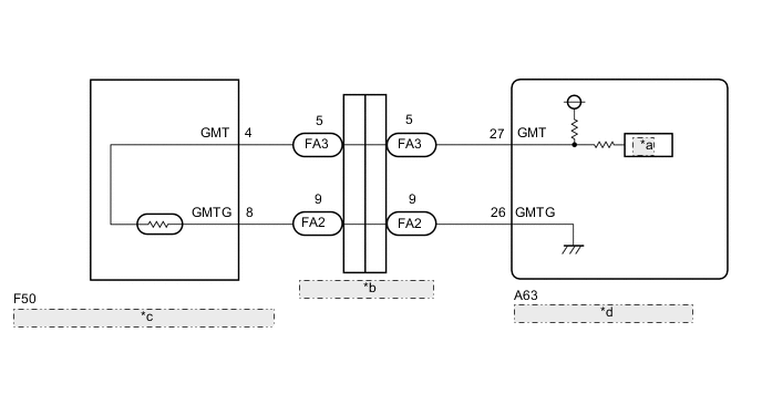
| *a | ADC |
| *b | Engine Wire Connector |
| *c | Hybrid Vehicle Transmission Assembly (Generator Temperature Sensor) |
| *d | Power Management Control ECU |
Figure 2. for RHD
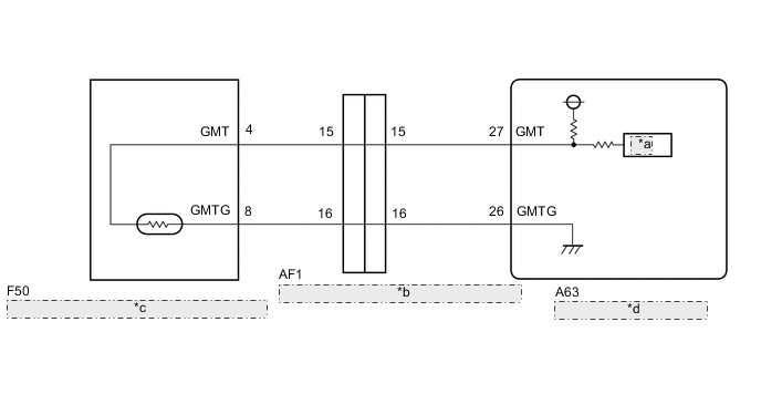
| *a | ADC |
| *b | No. 1 Engine Room Relay Block and No. 1 Junction Block Assembly Connector |
| *c | Hybrid Vehicle Transmission Assembly (Generator Temperature Sensor) |
| *d | Power Management Control ECU |
CAUTION / NOTICE / HINT
Tech Tips
After the repair, clear the DTCs and perform the following procedure to check that DTCs are not output.
-
Turn the power switch on (IG) and wait for 5 seconds or more.
PROCEDURE
-
CHECK CONNECTOR CONNECTION CONDITION (POWER MANAGEMENT CONTROL ECU CONNECTOR)
Result Result Proceed to OK A NG (The connector is not connected securely.) B NG (The terminals are not making secure contact or are deformed, or water or foreign matter exists in the connector.) C
-
Check the connection condition of the power management control ECU connectors and the contact pressure of each terminal. Check the terminals for deformation, and check the connector for water ingress and foreign matter.
OK - The connector is connected securely. - The terminals are not deformed and are connected securely. - No water or foreign matter in the connector. 
*A for LHD *B for RHD Result Result Proceed to OK A NG (The connector is not connected securely.) B NG (The terminals are not making secure contact or are deformed, or water or foreign matter exists in the connector.) C
B 
CONNECT SECURELY
C
REPAIR OR REPLACE HARNESS OR CONNECTOR
A 
-
-
READ VALUE USING GTS (MOTOR TEMP NO2)
-
Connect the GTS to the DLC3.
-
Turn the power switch on (IG).
-
Enter the following menus: Powertrain / Hybrid Control / Data List / Motor Temp No2.
Powertrain > Hybrid Control > Data ListTester Display Motor Temp No2 -
Read the Data List.
Result Proceed to -40°C (-40°F) 215°C (419°F) Same as actual temperature -
Turn the power switch off.
215°C (419°F) 
CHECK GENERATOR TEMPERATURE SENSOR Click here
Same as actual temperature
CHECK FOR INTERMITTENT PROBLEMS Click here
-40°C (-40°F)
-
-
CHECK POWER MANAGEMENT CONTROL ECU
-
Connect terminals 27 (GMT) and 26 (GMTG) of connector A63 of the power management control ECU.
-
Connect the GTS to the DLC3.
-
Turn the power switch on (IG).
-
Enter the following menus: Powertrain / Hybrid Control / Data List / Motor Temp No2.
Powertrain > Hybrid Control > Data ListTester Display Motor Temp No2 -
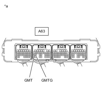
*a Component with harness connected
(Power Management Control ECU)
Read the Data List.
OK Tester Display Condition Specified Condition Motor Temp No2 Terminals A63-27 (GMT) and A63-26 (GMTG) connected
Power switch on (IG)
215°C (419°F) -
Turn the power switch off.
Result Proceed to OK NG
NG
REPLACE POWER MANAGEMENT CONTROL ECU Click here
OK
-
-
CHECK CONNECTOR CONNECTION CONDITION (GENERATOR TEMPERATURE SENSOR CONNECTOR)
-
Remove the hybrid vehicle transmission assembly.
-
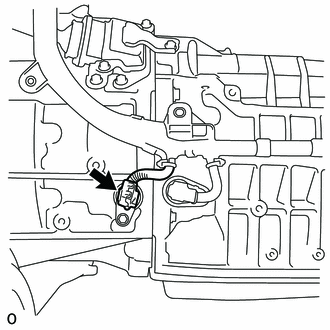
Check the connection condition of the generator temperature sensor connector and the contact pressure of each terminal.
-
Check the terminals for deformation, and check the connector for water ingress and foreign matter.
OK - The connector is connected securely. - The terminals are not deformed and are connected securely. - No water or foreign matter in the connector. Result Result Proceed to OK A NG (The connector is not connected securely.) B NG (The terminals are not making secure contact or are deformed, or water or foreign matter exists in the connector.) C
B
CONNECT SECURELY
C
REPAIR OR REPLACE HARNESS OR CONNECTOR
A
-
-
INSPECT HYBRID VEHICLE TRANSMISSION ASSEMBLY (GENERATOR TEMPERATURE SENSOR)
-
Disconnect the generator temperature sensor connector.
-
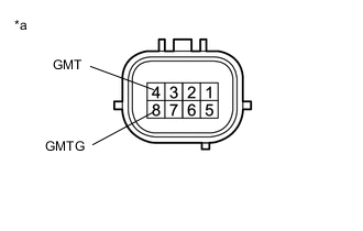
*a Component without harness connected
(Hybrid Vehicle Transmission Assembly (Generator Temperature Sensor))
Measure the resistance according to the value(s) in the table below.
Standard Resistance Tester Connection Switch Condition Specified Condition 4 (GMT) - 8 (GMTG) Power switch off 0.3436 to 1442 kΩ -
Reconnect the generator temperature sensor connector.
Result Proceed to OK NG
OK
REPAIR OR REPLACE HARNESS OR CONNECTOR
NG
REPLACE HYBRID VEHICLE TRANSMISSION ASSEMBLY Click here
-
-
CHECK GENERATOR TEMPERATURE SENSOR
-
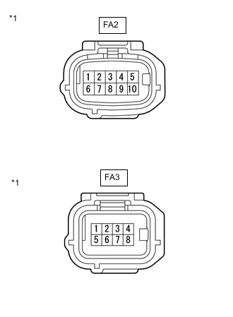
*1 Engine Wire Connector for LHD:
-
Disconnect the FA2 and FA3 engine wire connectors.
-
Measure the resistance according to the value(s) in the table below.
Standard Resistance Tester Connection Switch Condition Specified Condition FA3-5 - FA2-9 Power switch off 0.3436 to 1442 kΩ Standard Resistance (Check for Short) Tester Connection Switch Condition Specified Condition FA3-5 or FA2-9 - Body ground and other terminals Power switch off 10 kΩ or higher -
Reconnect the FA2 and FA3 engine wire connectors.
-
-

*1 No. 1 Engine Room Relay Block and No. 1 Junction Block Assembly Connector for RHD:
-
Disconnect the AF1 No. 1 engine room relay block and No. 1 junction block assembly connector.
-
Measure the resistance according to the value(s) in the table below.
Standard Resistance (Check for Open) Tester Connection Switch Condition Specified Condition AF1-15 - AF1-16 Power switch off 0.3436 to 1442 kΩ Standard Resistance (Check for Short) Tester Connection Switch Condition Specified Condition AF1-15 or AF1-16 - Body ground and other terminals Power switch off 10 kΩ or higher -
Reconnect the AF1 No. 1 engine room relay block and No. 1 junction block assembly connector.
Result Result Proceed to OK (for LHD) A OK (for RHD) B NG C -
B
CHECK HARNESS AND CONNECTOR (NO. 1 ENGINE ROOM RELAY BLOCK AND NO. 1 JUNCTION BLOCK ASSEMBLY - POWER MANAGEMENT CONTROL ECU) Click here
C
CHECK CONNECTOR CONNECTION CONDITION (GENERATOR TEMPERATURE SENSOR CONNECTOR) Click here
A
-
-
CHECK HARNESS AND CONNECTOR (ENGINE WIRE - POWER MANAGEMENT CONTROL ECU)
-
Disconnect the FA2 and FA3 engine room main wire connectors.
-
Disconnect the A63 power management control ECU connector.
-
Measure the resistance according to the value(s) in the table below.
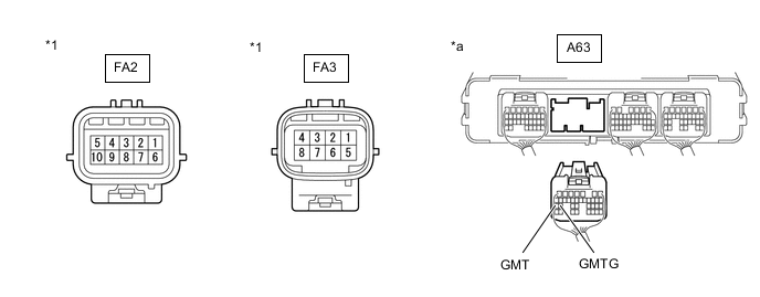
*1 Engine Room Main Wire Connector - - *a Rear view of wire harness connector
(to Power Management Control ECU)
- - Standard Resistance Tester Connection Condition Specified Condition FA3-5 - A63-27 (GMT) Power switch off Below 1 Ω FA2-9 - A63-26 (GMTG) Power switch off Below 1 Ω Standard Resistance (Check for Short) Tester Connection Condition Specified Condition FA3-5 or A63-27 (GMT) - Body ground and other terminals Power switch off 10 kΩ or higher FA2-9 or A63-26 (GMTG) - Body ground and other terminals Power switch off 10 kΩ or higher -
Reconnect the A63 power management control ECU connector.
-
Reconnect the FA2 and FA3 engine room main wire connectors.
Result Proceed to OK NG
OK
REPLACE POWER MANAGEMENT CONTROL ECU Click here
NG
REPAIR OR REPLACE HARNESS OR CONNECTOR (ENGINE WIRE - POWER MANAGEMENT CONTROL ECU)
-
-
CHECK HARNESS AND CONNECTOR (NO. 1 ENGINE ROOM RELAY BLOCK AND NO. 1 JUNCTION BLOCK ASSEMBLY - POWER MANAGEMENT CONTROL ECU)
-
Disconnect the AF1 No. 1 engine room relay block and No. 1 junction block assembly connector.
-
Disconnect the A63 power management control ECU connector.
-
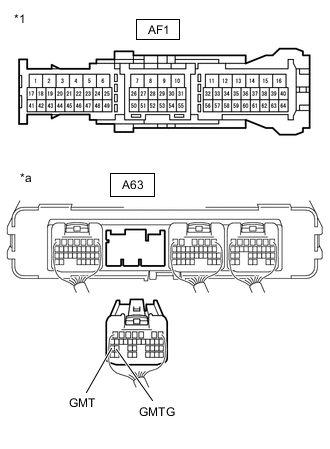
*1 No. 1 Engine Room Relay Block and No. 1 Junction Block Assembly Connector *a Rear view of wire harness connector
(to Power Management Control ECU)
Measure the resistance according to the value(s) in the table below.
Standard Resistance (Check for Open) Tester Connection Condition Specified Condition AF1-15 - A63-27 (GMT) Power switch off Below 1 Ω AF1-16 - A63-26 (GMTG) Power switch off Below 1 Ω Standard Resistance (Check for Short) Tester Connection Condition Specified Condition AF1-15 or A63-27 (GMT) - Body ground and other terminals Power switch off 10 kΩ or higher AF1-16 or A63-26 (GMTG) - Body ground and other terminals Power switch off 10 kΩ or higher -
Reconnect the A63 power management control ECU connector.
-
Reconnect the AF1 No. 1 engine room relay block and No. 1 junction block assembly connector.
Result Proceed to OK NG
OK
REPLACE POWER MANAGEMENT CONTROL ECU Click here
NG
REPAIR OR REPLACE HARNESS OR CONNECTOR (NO. 1 ENGINE ROOM RELAY BLOCK AND NO. 1 JUNCTION BLOCK ASSEMBLY - POWER MANAGEMENT CONTROL ECU)
-
-
CHECK CONNECTOR CONNECTION CONDITION (GENERATOR TEMPERATURE SENSOR CONNECTOR)
-
Remove the hybrid vehicle transmission assembly.
-
Check the connection condition of the generator temperature sensor connector and the contact pressure of each terminal.
-
Check the terminals for deformation, and check the connector for water ingress and foreign matter.
OK - The connector is connected securely. - The terminals are not deformed and are connected securely. - No water or foreign matter in the connector. Result Result Proceed to OK A NG (The connector is not connected securely.) B NG (The terminals are not making secure contact or are deformed, or water or foreign matter exists in the connector.) C
B
CONNECT SECURELY
C
REPAIR OR REPLACE HARNESS OR CONNECTOR
A
-
-
INSPECT HYBRID VEHICLE TRANSMISSION ASSEMBLY (GENERATOR TEMPERATURE SENSOR)
-
Disconnect the generator temperature sensor connector.
-
*a Component without harness connected
(Hybrid Vehicle Transmission Assembly (Generator Temperature Sensor))
Measure the resistance according to the value(s) in the table below.
Standard Resistance Tester Connection Switch Condition Specified Condition 4 (GMT) - 8 (GMTG) Power switch off 0.3436 to 1442 kΩ -
Reconnect the generator temperature sensor connector.
Result Proceed to OK NG
OK
REPAIR OR REPLACE HARNESS OR CONNECTOR (ENGINE WIRE)
NG
REPLACE HYBRID VEHICLE TRANSMISSION ASSEMBLY Click here
-