HYBRID CONTROL SYSTEM SYSTEM DESCRIPTION
-
OPERATION
-
Operation of Hybrid Vehicle
-
The hybrid system uses motive force provided by the engine and motor (MG2), and uses generator (MG1) as a generator. The system optimally combines these forces in accordance with various driving conditions.
-
The power management control ECU constantly monitors the engine coolant temperature, SOC, HV battery temperature and electrical load conditions. If any of the monitoring conditions fail to satisfy the requirements, the power switch is on (READY) and the shift position is any position other than N, the power management control ECU starts the engine.
-
The hybrid system drives the vehicle by optimally combining the operation of the engine, generator (MG1) and motor (MG2) in accordance with the driving conditions listed below. The vehicle conditions listed below are examples of typical vehicle driving conditions.
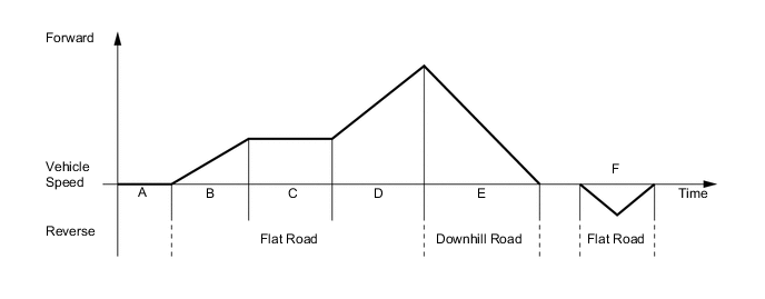
Driving Condition A Power switch on (READY) B Starting Off C Constant-speed Cruising D During Full Throttle Acceleration E During Deceleration F During Reverse
-
-
Driving Condition B: Starting Off
-
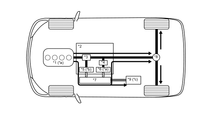
When the vehicle is started off, the vehicle operates powered by motor (MG2).
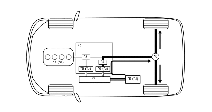
*1 Engine *2 Hybrid Vehicle Transmission Assembly *3 Power Split Planetary Gear *4 Motor Speed Reduction Planetary Gear *5 Generator (MG1) *6 Motor (MG2) *7 Inverter with Converter Assembly *8 Differential *9 HV Battery - - *a Stopped *b Rotates Freely *c Drive *d Discharge 
Power Transmission 
Mechanical Power Path 
Electrical Power Path (DC) 
Electrical Power Path (AC) -
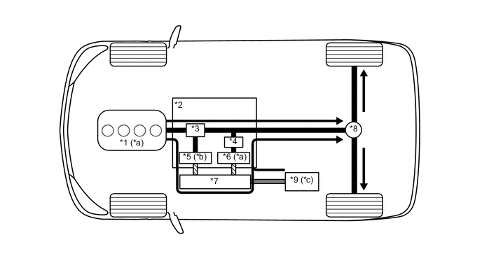
If the SOC of the HV battery is low, it is charged by generator (MG1) which is driven by the engine. The electricity from generator (MG1) is also used to drive motor (MG2).
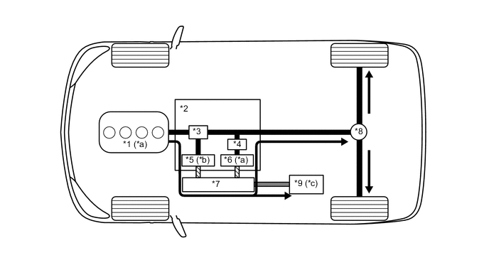
*1 Engine *2 Hybrid Vehicle Transmission Assembly *3 Power Split Planetary Gear *4 Motor Speed Reduction Planetary Gear *5 Generator (MG1) *6 Motor (MG2) *7 Inverter with Converter Assembly *8 Differential *9 HV Battery - - *a Drive *b Driven - Generates Electricity *c Charged by generator (MG1) - - Power Transmission Mechanical Power Path Electrical Power Path (DC) Electrical Power Path (AC)
-
-
Driving Condition C: during Low Load and Constant-speed Cruising
-
When the vehicle is running under constant-speed cruising conditions, the engine will be operated in its most efficient range to power the vehicle.
-
The motive force from the engine is split into two in the power split planetary gear. One portion of the motive force is used to drive the wheels directly and the other is used to generate electricity using generator (MG1).
-
The electricity from generator (MG1) is used to drive motor (MG2). This supports the directly transmitted engine motive force, contributing to fuel efficiency.
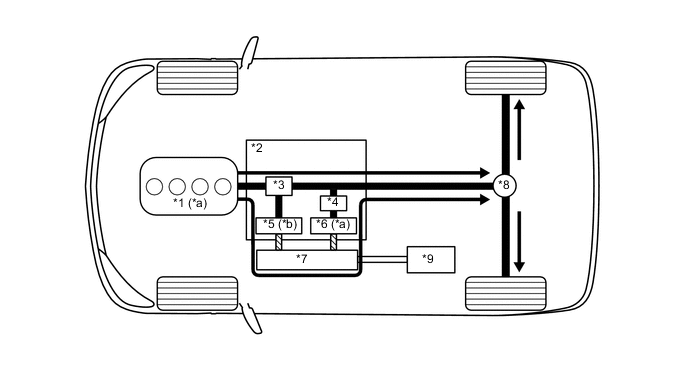
*1 Engine *2 Hybrid Vehicle Transmission Assembly *3 Power Split Planetary Gear *4 Motor Speed Reduction Planetary Gear *5 Generator (MG1) *6 Motor (MG2) *7 Inverter with Converter Assembly *8 Differential *9 HV Battery *10 - *a Drive *b Driven - Generates Electricity Power Transmission Mechanical Power Path Electrical Power Path (AC) - - -
If the SOC of the HV battery is low, more engine power is provided to increase the generation of electricity via generator (MG1). This charges the HV battery.
*1 Engine *2 Hybrid Vehicle Transmission Assembly *3 Power Split Planetary Gear *4 Motor Speed Reduction Planetary Gear *5 Generator (MG1) *6 Motor (MG2) *7 Inverter with Converter Assembly *8 Differential *9 HV Battery - - *a Drive *b Driven - Generates Electricity *c Charged by generator (MG1) - - Power Transmission Mechanical Power Path Electrical Power Path (DC) Electrical Power Path (AC)
-
-
Driving Condition D: during Full Throttle Acceleration
-
When the vehicle driving condition changes from low load cruising to full throttle acceleration, the system supplements the motive force of motor (MG2) with electrical power from the HV battery.
*1 Engine *2 Hybrid Vehicle Transmission Assembly *3 Power Split Planetary Gear *4 Motor Speed Reduction Planetary Gear *5 Generator (MG1) *6 Motor (MG2) *7 Inverter with Converter Assembly *8 Differential *9 HV Battery - - *a Drive *b Driven - Generates Electricity *c Discharge - - Power Transmission Mechanical Power Path Electrical Power Path (DC) Electrical Power Path (AC)
-
-
Driving Condition E: during Deceleration
-
While the vehicle is being driven with the shift lever in D and it decelerates, the engine turns off and the engine motive force output to the wheels will be zero. At this time, the wheels drive motor (MG2), causing motor (MG2) to operate as a generator and charge the HV battery. While motor (MG2) is operating as a generator, it creates a resistance to rotation at the wheels, producing a braking effect.
-
If the vehicle decelerates at a higher speed, the engine (crankshaft) will not stop turning. The engine will maintain a predetermined speed in order to protect the planetary gear unit. This operation is not shown in the following diagrams:
*1 Engine *2 Hybrid Vehicle Transmission Assembly *3 Power Split Planetary Gear *4 Motor Speed Reduction Planetary Gear *5 Generator (MG1) *6 Motor (MG2) *7 Inverter with Converter Assembly *8 Differential *9 HV Battery - - *a Stopped *b Rotates Freely *c Driven - Generates Electricity *d Charged by motor (MG2) Power Transmission Mechanical Power Path Electrical Power Path (DC) Electrical Power Path (AC)
-
-
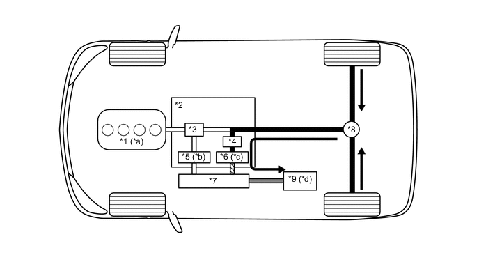
Driving Condition F: Driving in Reverse
-
While the vehicle is being driven in reverse, its power is delivered by motor (MG2). At this time, motor (MG2) is spinning in the opposite (-) direction of forward travel, the engine can remain stopped, and generator (MG1) is spinning in the (+) direction without generating electricity.
-
While driving in reverse, when any of the conditions monitored by the power management control ECU, such as the SOC of the HV battery, HV battery temperature, engine coolant temperature and electrical load condition, reach a specified level, generator (MG1) will be used to start the engine. The following illustration represents an example when the engine is not running:
*1 Engine *2 Hybrid Vehicle Transmission Assembly *3 Power Split Planetary Gear *4 Motor Speed Reduction Planetary Gear *5 Generator (MG1) *6 Motor (MG2) *7 Inverter with Converter Assembly *8 Differential *9 HV Battery - - *a Stopped *b Rotates Freely *c Drive *d Discharge Power Transmission Mechanical Power Path Electrical Power Path (DC) Electrical Power Path (AC)
-
-
-
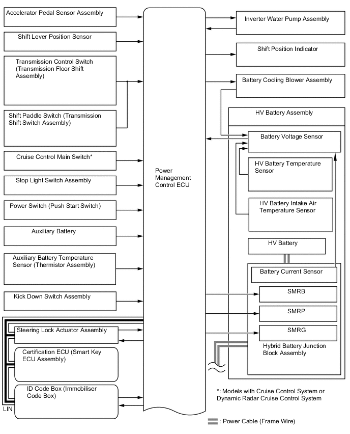
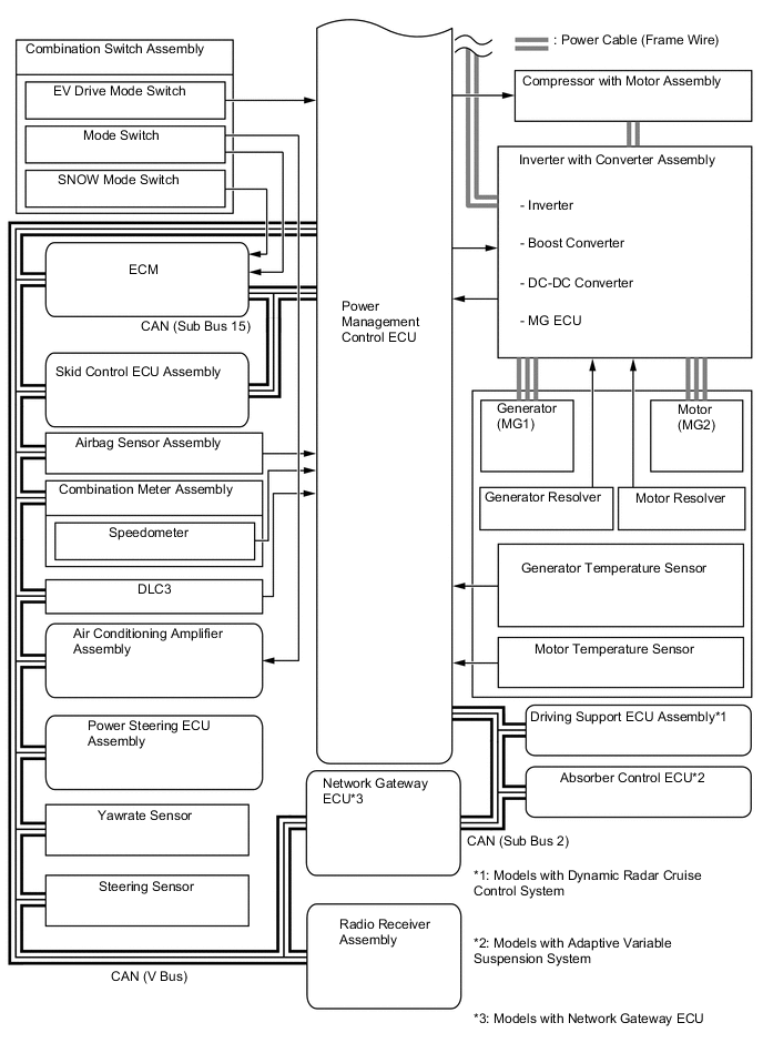
SYSTEM DIAGRAM
-
FUNCTION OF MAIN COMPONENTS
-
The main components of the hybrid system have the following functions:
Component Function Power Management Control ECU
-
Performs comprehensive control of the hybrid system.
-
Information from various sensors as well as from ECUs (ECM, MG ECU, battery voltage sensor and skid control ECU Assembly) is received, and based on this the required torque and output power is calculated. The power management control ECU transmits the calculated result to the ECM, MG ECU and skid control ECU assembly.
-
Monitors the SOC of the HV battery.
-
Controls the DC-DC converter.
-
Controls the inverter water pump assembly.
-
Controls the battery cooling blower assembly.
2AR-FSE Engine The 2AR-FSE engine is a high-expansion ratio Atkinson cycle engine which is compatible with the hybrid system and which generates drive force for driving and energy for electricity generation. L210 Hybrid Vehicle Transmission Assembly Generator (MG1) Generator (MG1), which is driven by the engine, generates high-voltage electricity in order to operate motor (MG2) and charge the HV battery. Also, it functions as a starter to start the engine. Motor (MG2)
-
Motor (MG2), which is driven by electrical power from generator (MG1) and the HV battery, generates motive force for the drive wheels.
-
During braking, or when the accelerator pedal is not depressed, it generates high-voltage electricity to recharge the HV battery.
Generator Resolver Detects the rotor position, rotational speed and direction of generator (MG1). Motor Resolver Detects the rotor position, rotational speed and direction of motor (MG2). Generator Temperature Sensor Detects the temperature of generator (MG1). Motor Temperature Sensor Detects the temperature of motor (MG2). Compound Gear Unit Power Split Planetary Gear Unit Distributes the engine motive force as appropriate to directly drive the vehicle as well as generator (MG1). Motor Speed Reduction Planetary Gear Unit Reduces the rotational speed of motor (MG2) in accordance with the characteristics of the planetary gear, in order to increase torque. Inverter with Converter Assembly Inverter Converts the direct current from the boost converter into alternating current for generator (MG1) and motor (MG2), and vice versa (from AC to DC). Boost Converter Boosts the HV battery nominal voltage of DC 230.4 V up to a maximum voltage of DC 650 V and vice versa (steps down DC 650 V to DC 230.4 V). DC-DC Converter Steps down the HV battery nominal voltage of DC 230.4 V to approximately DC 14 V in order to supply electricity to the electrical components, as well as to recharge the auxiliary battery. MG ECU Controls the inverter and boost converter in accordance with the signals received from the power management control ECU, thus operating generator (MG1) and motor (MG2) as either a generator or motor. Atmospheric Pressure Sensor Detects the atmospheric pressure. Temperature Sensor for Inverter with Converter Assembly Detects temperatures in the parts of the inverter with converter assembly as well as the HV coolant temperature. Inverter Current Sensor Detects the current of generator (MG1) and motor (MG2). HV Battery Assembly HV Battery (Battery Modules)
-
Supplies electrical power to generator (MG1) and motor (MG2) in accordance with the driving conditions of the vehicle.
-
Recharged by generator (MG1) and motor (MG2) in accordance with the SOC and the driving conditions of the vehicle.
HV Battery Temperature Sensor Detects temperatures in the parts of the HV battery. HV Battery Intake Air Temperature Sensor Detects the intake air temperature from the battery cooling blower assembly. Hybrid Battery Junction Block Assembly System Main Relays Connects and disconnects the high-voltage circuit between the HV battery and the inverter with converter assembly through the use of signals from the power management control ECU. HV Battery Current Sensor Detects the input and output current of the HV battery. Battery Voltage Sensor
-
Monitors the conditions of the HV battery such as voltage, current and temperature, and transmits this information to the power management control ECU.
-
Monitors the high-voltage system for breakdown of the electrical insulation.
Service Plug Grip Shuts off the high-voltage circuit of the HV battery when the service plug grip is removed for vehicle inspection or maintenance. Interlock Switch (for Service Plug Grip/for Inverter Terminal Cover/for Connector Cover Assembly/for Power Cable Connector) Verifies that the service plug grip, inverter terminal cover, connector cover assembly and inverter power cable connector are installed. Power Cable (Frame Wire) Connects the HV battery, inverter with converter assembly, hybrid vehicle transmission assembly and compressor with motor assembly. Inverter Water Pump Assembly Controlled in 4 stages by the power management control ECU in accordance with inverter coolant temperatures in order to cool the inverter coolant. Battery Cooling Blower Assembly Operates under the control of the power management control ECU in order to cool the HV battery. Auxiliary Battery Supplies electricity to the electrical components. Auxiliary Battery Temperature Sensor (Thermistor Assembly) Detects the temperature of the auxiliary battery. Power Switch Starts and stops the hybrid system. Accelerator Pedal Sensor Assembly Converts the accelerator pedal position into an electrical signal and sends it to the power management control ECU. Kick Down Switch Assembly Detects that the accelerator pedal is almost fully depressed. Cruise Control Main Switch*1 Turns the cruise control system and dynamic radar cruise control system on and off, and conducts various operations including vehicle speed setting, acceleration, deceleration and control cancellation. Shift Paddle Switch (Transmission Shift Switch Assembly) Detects the driver's shift-up and shift-down operations. Transmission Control Switch (Transmission Floor Shift Assembly)
-
Detects that the shift lever is in S.
-
Detects the driver's shift-up and shift-down operations when the shift lever is in S.
Shift Lever Position Sensor Converts the shift position into electrical signals and sends them to the power management control ECU. Stop Light Switch Assembly Detects the depression of the brake pedal. Combination Switch Assembly EV Drive Mode Switch Sends the EV drive mode switch signal to the power management control ECU when operated by the driver. Mode Switch
-
Outputs the NORMAL mode signal to the power management control ECU via the ECM when operated by the driver.
-
Outputs the ECO mode signal to the power management control ECU via the air conditioning amplifier assembly when operated by the driver.
-
Outputs the SPORT*2 or SPORT S/S+*3 mode signal to the power management control ECU via the ECM when operated by the driver.
SNOW Mode Switch Outputs the SNOW mode switch signal to the power management control ECU via the ECM when operated by the driver. ECM
-
Performs control of the engine in accordance with the target engine speed and required engine motive force received from the power management control ECU.
-
Transmits various engine operating condition signals to the power management control ECU.
Skid Control ECU Assembly
-
During braking, it calculates the required regenerative braking force and transmits it to the power management control ECU.
-
Transmits the request to the power management control ECU to limit motive force while the TRC or VSC is operating.
Air Conditioning Amplifier Assembly Transmits various air conditioning state signals to the power management control ECU. Airbag Sensor Assembly During a collision, it transmits the airbag deployment signal to the power management control ECU. Driving Support ECU Assembly*4 Sends the information about the operation conditions of the dynamic radar cruise control system to the power management control ECU. Radio Receiver Assembly
-
Displays hybrid system output and charging of the hybrid battery on the energy monitor in the multi-display.
-
Displays drive mode on the multi-display.
Combination Meter Assembly Hybrid System Indicator Displays the system power output and regenerative charging of the hybrid system. When SPORT*2, SPORT S*3 or SPORT S+*3 mode is selected, the tachometer replaces the hybrid system indicator. READY Indicator Light Informs the driver that the vehicle is ready to drive. Master Warning Light Illuminates or flashes and the buzzer may sound depending on the message displayed on the multi-information display. EV Drive Indicator Light Turns on during EV driving. Charge Warning Light Turns on when there is a malfunction in the auxiliary battery charging system. Malfunction Indicator Lamp (MIL) Turns on when there is a malfunction in the hybrid control system and engine control system. Multi-information Display
-
Displays the shift lever position.
-
Displays the shift range.
-
Displays the energy flow.
-
Displays the EV mode.
-
Displays the drive mode.
-
Displays the SNOW mode.
-
Displays messages to inform the driver when a malfunction occurs.
-
Shows system status and appropriate operations to be performed.
*1: Models with cruise control system or dynamic radar cruise control system
*2: Models without adaptive variable suspension system
*3: Models with adaptive variable suspension system
*4: Models with dynamic radar cruise control system
-
-