SFI SYSTEM(w/o EGR System) MIL Circuit
DESCRIPTION
The MIL (Malfunction Indicator Lamp) is used to indicate vehicle malfunctions detected by the ECM. When the power switch is turned on (IG), power is supplied to the MIL circuit, and the ECM provides the circuit ground which illuminates the MIL.
The MIL operation can be checked visually: When the power switch is turned on (IG), the MIL should be illuminated and should turn off after power switch on (READY). If the MIL remains illuminated or is not illuminated, conduct the following troubleshooting procedure using the GTS.
WIRING DIAGRAM
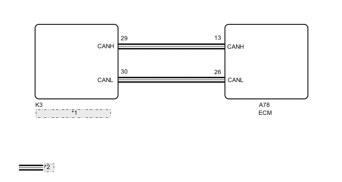
| *1 | Combination Meter Assembly |
| *2 | CAN Communication Line |
PROCEDURE
-
CHECK THAT MIL IS ILLUMINATED
-
Perform troubleshooting in accordance with the table below.
Result Result Condition Proceed to Illuminates → Turns off Power switch on (IG) → power switch on (READY) A Other than above - B
A 
CHECK FOR INTERMITTENT PROBLEMS Click here
B 
-
-
CHECK CONNECTION BETWEEN GTS AND ECM
-
Connect the GTS to the DLC3.
-
Turn the power switch on (IG).
-
Turn the GTS on.
-
Check for communication between the GTS and ECM.
Tech Tips
It can be checked using the "Engine and ECT" item of the Data List.
Result Result Proceed to Communication is not possible A Communication is possible B
B
GO TO VC OUTPUT CIRCUIT Click here
A
-
-
CHECK WHETHER DTC OUTPUT RECURS
-
Connect the GTS to the DLC3.
-
Turn the power switch on (IG).
-
Turn the GTS on.
-
Enter the following menus: Powertrain / Engine and ECT / Trouble Codes.
Powertrain > Engine and ECT > Trouble Codes -
Check if any DTCs have been detected. Note down any DTCs.
Result Result Proceed to DTC is not output A Any DTCs is output B Tech Tips
Check for detected DTCs output from other ECUs which relate to the MIL.
B
REPAIR CIRCUITS INDICATED BY OUTPUT DTCS
A
-
-
PERFORM ACTIVE TEST USING GTS
-
Connect the GTS to the DLC3.
-
Turn the power switch on (IG).
-
Turn the GTS on.
-
Enter the following menus: Body Electrical / Combination Meter / Active Test / Check Engine Indicator.
Body Electrical > Combination Meter > Active TestTester Display Check Engine Indicator -
Check the status of the MIL while performing the Active Test.
Result Result Proceed to Changes A Does not change B
A
REPLACE ECM Click here
B
REPLACE COMBINATION METER ASSEMBLY Click here
-