POWER WINDOW CONTROL SYSTEM Driver Side Power Window Auto Up / Down Function does not Operate with Power Window Master Switch
DESCRIPTION
If the manual up and down function operates normally but the auto up and down function does not, then fail-safe mode may be functioning.
If power window initialization has not been performed, the auto up and down function will not operate.
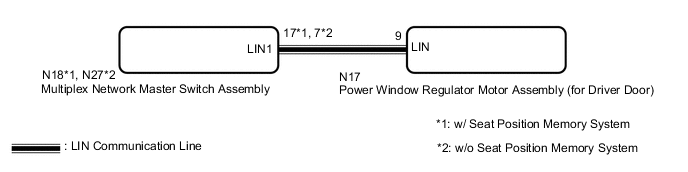
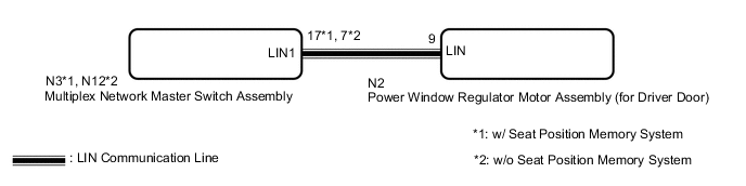
WIRING DIAGRAM
-
for LHD
-
for RHD
CAUTION / NOTICE / HINT
Note
-
The power window control system uses the LIN communication system. Inspect the communication function by following How to Proceed with Troubleshooting. Troubleshoot the power window control system after confirming that the communication system is functioning properly.
-
If the power window regulator motor assembly (for driver door) has been replaced with a new one, initialize the power window control system.
Tech Tips
If the pulse sensor built into the power window regulator motor assembly (for driver door) is malfunctioning, the power window control system enters fail-safe mode. The remote up and down and auto up and down functions cannot be operated during fail-safe mode. However, the power window can be closed by holding the multiplex network master switch assembly at the auto up position, and opened manually by pushing down the multiplex network master switch assembly.
PROCEDURE
-
READ VALUE USING GTS (MASTER SWITCH)
-
Connect the GTS to the DLC3.
-
Turn the power switch on (IG).
-
Turn the GTS on.
-
Enter the following menus: Body Electrical / Master switch / Data List.
-
Read the Data List according to the display on the GTS.
Body Electrical > Master Switch > Data ListTester Display Measurement Item Range Normal Condition Diagnostic Note D Door P/W Auto SW Driver door power window auto switch signal OFF or ON OFF: Driver door power window auto switch not being operated
ON: Driver door power window auto switch being operated
-
Body Electrical > Master Switch > Data ListTester Display D Door P/W Auto SW OK On the GTS screen, ON or OFF is displayed accordingly. Result Proceed to OK NG
NG 
REPLACE MULTIPLEX NETWORK MASTER SWITCH ASSEMBLY Click here
OK 
-
-
READ VALUE USING GTS (D-DOOR MOTOR)
-
Enter the following menus: Body Electrical / D-Door Motor / Data List.
-
Read the Data List according to the display on the GTS.
Body Electrical > D-Door Motor > Data ListTester Display Measurement Item Range Normal Condition Diagnostic Note D Door P/W Auto SW Driver door power window auto switch signal OFF or ON OFF: Driver door power window auto switch not being operated
ON: Driver door power window auto switch being operated
-
Body Electrical > D-Door Motor > Data ListTester Display D Door P/W Auto SW OK On the GTS screen, ON or OFF is displayed accordingly. Result Proceed to OK NG
NG 
REPLACE MULTIPLEX NETWORK MASTER SWITCH ASSEMBLY Click here
OK
-
-
PERFORM INITIALIZATION (FOR DRIVER DOOR)
-
Initialize the power window regulator motor assembly (for driver door).
Result Proceed to NEXT
NEXT
-
-
CHECK POWER WINDOW CONTROL SYSTEM (AUTO UP / DOWN FUNCTION)
-
Check that the driver door power window moves when the auto up and down function of the multiplex network master switch assembly is operated.
OK Driver door auto up and down function is normal. Result Proceed to OK NG
OK
END (PROBLEM DUE TO INITIALIZATION FAILURE)
NG
REPLACE POWER WINDOW REGULATOR MOTOR ASSEMBLY (FOR DRIVER DOOR) Click here
-
-
REPLACE MULTIPLEX NETWORK MASTER SWITCH ASSEMBLY
-
Replace the multiplex network master switch assembly.
Result Proceed to NEXT
NEXT
-
-
CHECK POWER WINDOW CONTROL SYSTEM (AUTO UP / DOWN FUNCTION)
-
Check that the driver door power window moves when the auto up and down function of the multiplex network master switch assembly is operated.
OK Driver door auto up and down function is normal. Result Proceed to OK NG
OK
END (MULTIPLEX NETWORK MASTER SWITCH ASSEMBLY WAS DEFECTIVE)
NG
REPLACE POWER WINDOW REGULATOR MOTOR ASSEMBLY (FOR DRIVER DOOR) Click here
-