PROCEDURE
- Click here
INSTALL CONSOLE BOX ASSEMBLY
-
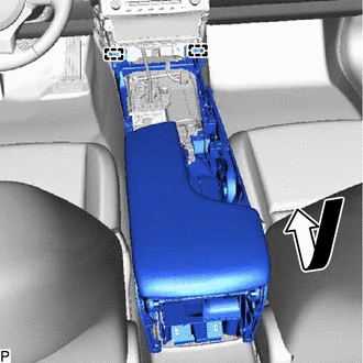
Engage the 2 guides as shown in the illustration.
-
Install the console box assembly with the 6 bolts.
-
Connect each connector.
-
- Click here
INSTALL CONSOLE BOX REGISTER ASSEMBLY
-
Engage the 6 claws, 2 clips and guide to install the console box register assembly.
-
- Click here
INSTALL INSTRUMENT PANEL CUP HOLDER
-
Install the instrument panel cup holder with the 4 screws.
-
- Click here
INSTALL NO. 2 CONSOLE BOX SILENCER PAD
-
Install the 2 No. 2 console box silencer pads.
-
- Click here
INSTALL LEXUS DISPLAY AUDIO CONTROLLER (for Radio and Display Type)
- Click here
INSTALL REMOTE TOUCH (for Multi-Media Module Receiver Type)
- Click here
INSTALL CONSOLE PANEL SUB-ASSEMBLY
-
Connect each connector.
-
Engage the 11 claws, clip and 7 guides.
-
Move the shift lever to P.
-
Install the console panel sub-assembly with the screw.
-
- Click here
INSTALL FRONT NO. 2 CONSOLE BOX INSERT
-
Push the front No. 2 console box insert in the direction indicated by the arrow (1) in the illustration to engage the guide.
-
Push the front No. 2 console box insert in the direction indicated by the arrow (2) in the illustration to engage the clip to install the front No. 2 console box insert.
-
- Click here
INSTALL FRONT NO. 1 CONSOLE BOX INSERT
-
Push the front No. 1 console box insert in the direction indicated by the arrow (1) in the illustration to engage the guide.
-
Push the front No. 1 console box insert in the direction indicated by the arrow (2) in the illustration to engage the clip to install the front No. 1 console box insert.
-
- Click here
INSTALL FRONT PANEL GARNISH RH
-
Engage the 5 clips.
-
Install the front panel garnish RH with the 2 screws.
-
- Click here
INSTALL FRONT PANEL GARNISH LH
-
Engage the 5 clips.
-
Install the front panel garnish LH with the 2 screws.
-
- Click here
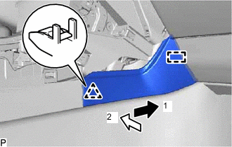
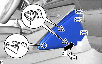
INSTALL INSTRUMENT PANEL FINISH PANEL END RH
-
for Hard Type:
-
Push the instrument panel finish panel end RH in the direction indicated by the arrow (1) in the illustration to engage the 3 guides.
-
Push the instrument panel finish panel end RH in the direction indicated by the arrow (2) in the illustration to engage the 3 clips to install the instrument panel finish panel end RH.
-
-
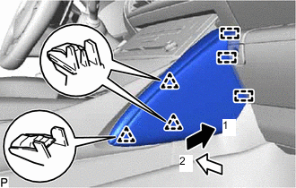
for Soft Type:
-
Push the instrument panel finish panel end RH in the direction indicated by the arrow (1) in the illustration to engage the 3 guides.
-
Push the instrument panel finish panel end RH in the direction indicated by the arrow (2) in the illustration to engage the claw and 2 clips to install the instrument panel finish panel end RH.
-
-
- Click here
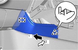
INSTALL INSTRUMENT PANEL FINISH PANEL END LH
-
for Hard Type:
-
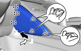
Push the instrument panel finish panel end LH in the direction indicated by the arrow (1) in the illustration to engage the 3 guides.
-
Push the instrument panel finish panel end LH in the direction indicated by the arrow (2) in the illustration to engage the 3 clips to install the instrument panel finish panel end LH.
-
-
for Soft Type:
-
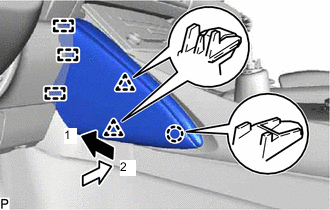
Push the instrument panel finish panel end LH in the direction indicated by the arrow (1) in the illustration to engage the 3 guides.
-
Push the instrument panel finish panel end LH in the direction indicated by the arrow (2) in the illustration to engage the claw and 2 clips to install the instrument panel finish panel end LH.
-
-
- Click here
INSTALL SHIFT LEVER KNOB SUB-ASSEMBLY
-
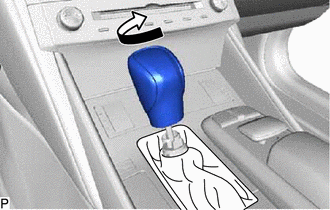
Turn the shift lever knob sub-assembly clockwise to install it.
-
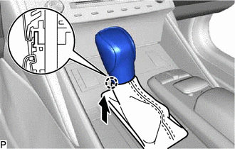
Engage the claw to connect the shift hole cover sub-assembly as shown in the illustration.
-