FRONT CONSOLE BOX REMOVAL
PROCEDURE
-
REMOVE SHIFT LEVER KNOB SUB-ASSEMBLY
-
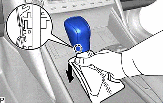
Disengage the claw and disconnect the shift hole cover sub-assembly as shown in the illustration.
-
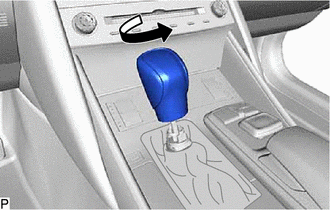
Turn the shift lever knob sub-assembly counterclockwise and remove it.
-
-
REMOVE INSTRUMENT PANEL FINISH PANEL END LH
-
for Hard Type:
-
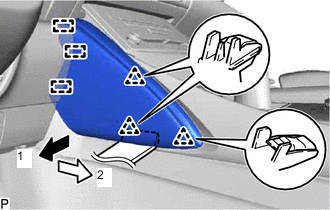
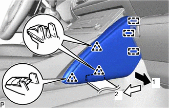
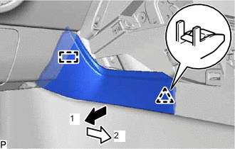
Using a moulding remover, disengage the 3 clips in the direction indicated by the arrow (1) in the illustration.
-
Pull the instrument panel finish panel end LH in the direction indicated by the arrow (2) in the illustration to disengage the 3 guides and remove the instrument panel finish panel end LH.
-
-
for Soft Type:
-
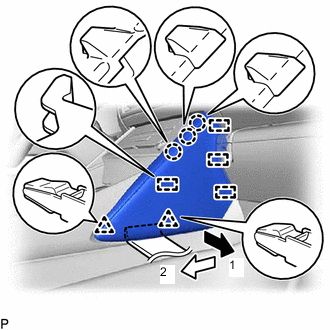
Using a moulding remover, disengage the 2 clips and 3 claws in the direction indicated by the arrow (1) in the illustration.
-
Pull the instrument panel finish panel end LH in the direction indicated by the arrow (2) in the illustration to disengage the 4 guides to remove the instrument panel finish panel end LH.
-
-
-
REMOVE INSTRUMENT PANEL FINISH PANEL END RH
-
for Hard Type:
-
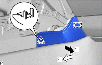
Using a moulding remover, disengage the 3 clips in the direction indicated by the arrow (1) in the illustration.
-
Pull the instrument panel finish panel end RH in the direction indicated by the arrow (2) in the illustration to disengage the 3 guides and remove the instrument panel finish panel end RH.
-
-
for Soft Type:
-
Using a moulding remover, disengage the 2 clips and 3 claws in the direction indicated by the arrow (1) in the illustration.
-
Pull the instrument panel finish panel end RH in the direction indicated by the arrow (2) in the illustration to disengage the 4 guides to remove the instrument panel finish panel end RH.
-
-
-
REMOVE FRONT PANEL GARNISH LH
-
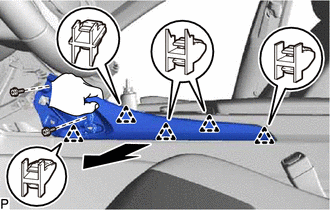
Remove the 2 screws.
-
Disengage the 5 clips to remove the front panel garnish LH.
-
-
REMOVE FRONT PANEL GARNISH RH
-
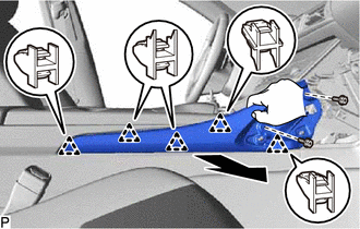
Remove the 2 screws.
-
Disengage the 5 clips to remove the front panel garnish RH.
-
-
REMOVE FRONT NO. 1 CONSOLE BOX INSERT
-
Disengage the clip in the direction indicated by the arrow (1) in the illustration.
-
Pull the front No. 1 console box insert in the direction indicated by the arrow (2) in the illustration to disengage the guide and remove the front No. 1 console box insert.
-
-
REMOVE FRONT NO. 2 CONSOLE BOX INSERT
-
Disengage the clip in the direction indicated by the arrow (1) in the illustration.
-
Pull the front No. 2 console box insert in the direction indicated by the arrow (2) in the illustration to disengage the guide and remove the front No. 2 console box insert.
-
-
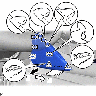
REMOVE CONSOLE PANEL SUB-ASSEMBLY
-
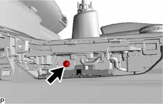
Remove the screw.
-
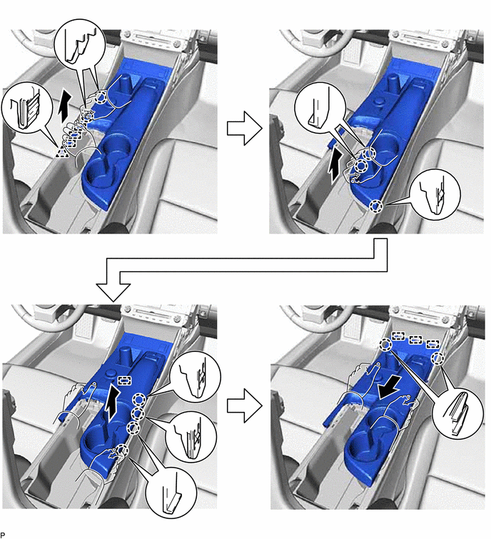
Move the shift lever to N.
-
Disengage the 11 claws, clip and 7 guides as shown in the illustration.
-
Disconnect each connector to remove the console panel sub-assembly.
-
-
REMOVE LEXUS DISPLAY AUDIO CONTROLLER (for Radio and Display Type)
-
REMOVE REMOTE TOUCH (for Multi-Media Module Receiver Type)
-
REMOVE INSTRUMENT PANEL CUP HOLDER
-
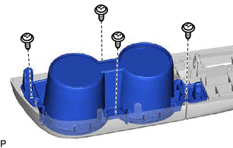
Remove the 4 screws and instrument panel cup holder.
-
-
REMOVE CONSOLE BOX REGISTER ASSEMBLY
-
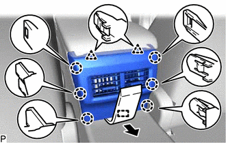
Using a moulding remover, disengage the 6 claws, 2 clips and guide and remove the console box register assembly as shown in the illustration.
-
-
REMOVE CONSOLE BOX ASSEMBLY
-
Disconnect each connector.
-
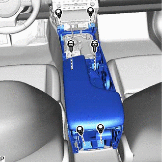
Remove the 6 bolts.
-
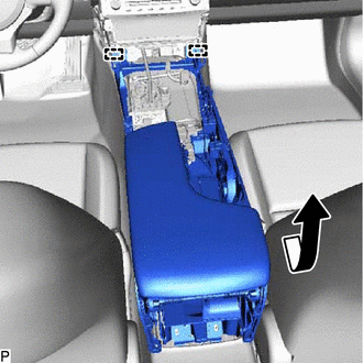
Pull the rear part of the console box assembly as shown in the illustration to disengage the 2 guides and remove the console box assembly.
-