Click here
-
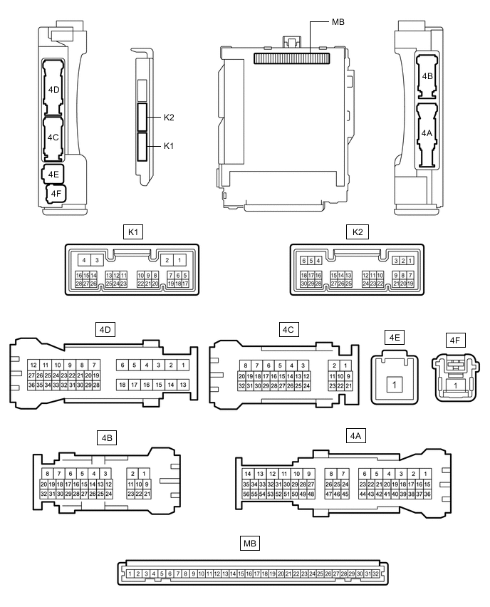
CHECK INSTRUMENT PANEL JUNCTION BLOCK ASSEMBLY AND MAIN BODY ECU (MULTIPLEX NETWORK BODY ECU)
-
Remove the main body ECU (multiplex network body ECU) from the instrument panel junction block assembly.
-
Reconnect the instrument panel junction block assembly connectors.
-
Measure the voltage and resistance according to the value(s) in the table below.
Tip:Measure the values on the wire harness side with the connector disconnected.
Tester Connection Wiring Color Terminal Description Condition Specified Condition MB-11 (GND1) - Body ground - Ground Always Below 1 Ω MB-31 (BECU) - Body ground - Auxiliary battery power supply Power switch off 11 to 14 V MB-32 (IG) - Body ground - IG power supply Power switch on (IG) 11 to 14 V MB-32 (IG) - Body ground - IG power supply Power switch off Below 1 V MB-30 (ACC) - Body ground - ACC power supply Power switch on (ACC) 11 to 14 V MB-30 (ACC) - Body ground - ACC power supply Power switch off Below 1 V If the result is not as specified, there may be a malfunction in the wire harness.
-
Install the main body ECU (multiplex network body ECU) to the instrument panel junction block assembly.
-
Measure the voltage according to the value(s) in the table below.
Tester Connection Wiring Color Terminal Description Condition Specified Condition K1-16 (REV) - Body ground R - Body ground Reverse signal Power switch on (IG), shift lever in any position other than R 11 to 14 V K1-16 (REV) - Body ground R - Body ground Reverse signal Power switch on (IG), shift lever in R Below 1 V If the result is not as specified, the main body ECU (multiplex network body ECU) may be malfunctioning.
-
-
CHECK REAR SUNSHADE RELAY
-

Disconnect the Q39 rear sunshade relay connector.
-
Measure the voltage and resistance according to the value(s) in the table below.
Tip:Measure the values on the wire harness side with the connector disconnected.
Tester Connection Wiring Color Terminal Description Condition Specified Condition Q39-8 (B) - Body ground B - Body ground Auxiliary battery power supply Power switch off 11 to 14 V Q39-7 (IG) - Body ground B - Body ground IG power supply Power switch off Below 1 V Q39-7 (IG) - Body ground B - Body ground IG power supply Power switch on (IG) 11 to 14 V Q39-1 (E) - Body ground W-B - Body ground Ground Always Below 1 Ω If the result is not as specified, there may be a malfunction in the wire harness.
-
Reconnect the Q39 rear sunshade relay connector.
-
Measure the voltage according to the value(s) in the table below.
Tester Connection Wiring Color Terminal Description Condition Specified Condition Q39-3 (REV) - Q39-1 (E) R - W-B Reverse signal Power switch on (IG), shift lever in any position other than R 11 to 14 V Q39-3 (REV) - Q39-1 (E) R - W-B Reverse signal Power switch on (IG), shift lever in R Below 1 V Q39-5 (SW) - Q39-1 (E) L - W-B Rear sunshade switch assembly signal Power switch on (IG), rear sunshade switch assembly not pushed 11 to 14 V Q39-5 (SW) - Q39-1 (E) L - W-B Rear sunshade switch assembly signal Power switch on (IG), rear sunshade switch assembly pushed and held Below 1 V If the result is not as specified, the rear sunshade relay may be malfunctioning.
-