COMPRESSOR REMOVAL
PROCEDURE
-
RECOVER REFRIGERANT FROM REFRIGERATION SYSTEM
-
REMOVE SERVICE PLUG GRIP
-
REMOVE ENGINE UNDER COVER
-
REMOVE REAR ENGINE UNDER COVER LH
-
CHECK TERMINAL VOLTAGE
-
Remove the connector cover assembly.
-
Check the terminal voltage.
-
Install the connector cover assembly.
-
-
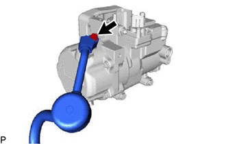
DISCONNECT SUCTION HOSE
-
Remove the bolt and disconnect the suction hose from the compressor with motor assembly.
-
Remove the O-ring from the suction hose.
Note
Seal the openings of the disconnected parts using vinyl tape to prevent moisture and foreign matter from entering them.
-
-
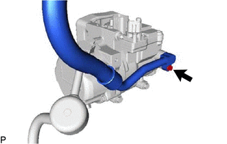
DISCONNECT NO. 1 COOLER REFRIGERANT DISCHARGE HOSE
-
Remove the bolt and disconnect the No. 1 cooler refrigerant discharge hose from the compressor with motor assembly.
-
Remove the O-ring from the No. 1 cooler refrigerant discharge hose.
Note
Seal the openings of the disconnected parts using vinyl tape to prevent moisture and foreign matter from entering them.
-
-
REMOVE COMPRESSOR WITH MOTOR ASSEMBLY
-
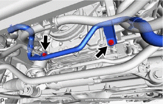
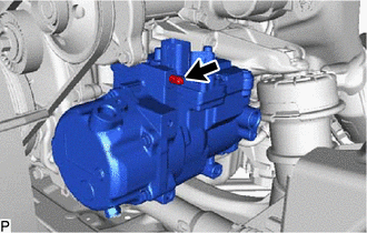
Remove the 2 bolts to disconnect the No. 1 inverter cooling pipe assembly.
-
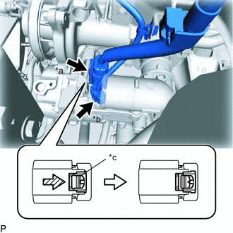
*a Connector A *b Connector B *c Green-colored Lock Using a screwdriver, slide the green-colored lock of the connector A as shown in the illustration to release it and disconnect the connector.
CAUTION:
Make sure to wear insulating gloves.
Note
Insulate the removed terminals and connector with insulating tape.
-
Disconnect the connector B.
-
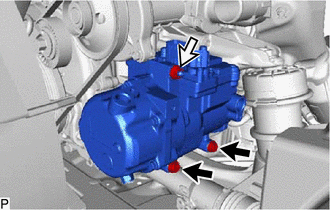

Bolt 
Nut Remove the 2 bolts and nut.
-
Using an E8 "TORX" socket wrench, remove the stud bolt and compressor with motor assembly.
-