AIR CONDITIONING SYSTEM Heater Water Pump Circuit
DESCRIPTION
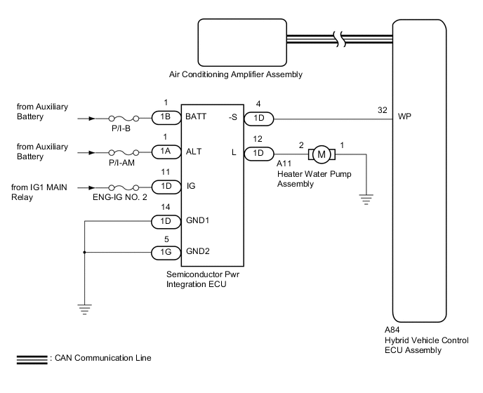
The heater water pump assembly sends engine coolant to the heater core assembly while the engine is stopped to prevent heater effectiveness from becoming low. Directed by the air conditioning amplifier assembly, the hybrid vehicle control ECU assembly operates the semiconductor pwr integration ECU and drives the heater water pump assembly.
WIRING DIAGRAM
CAUTION / NOTICE / HINT
Note
Inspect the fuses for circuits related to this system before performing the following inspection procedure.
PROCEDURE
-
CHECK CAN COMMUNICATION SYSTEM
-
Using the GTS, check if the CAN communication system is functioning normally.
Result Result Proceed to CAN communication system DTCs are not output A CAN communication system DTCs are output B
B 
GO TO CAN COMMUNICATION SYSTEM Click here
A 
-
-
CHECK SEMICONDUCTOR PWR INTEGRATION ECU
-
Using a voltmeter, check the signal reading of the semiconductor pwr integration ECU.
OK A normal signal reading is output. Result Proceed to OK NG
NG
CHECK SEMICONDUCTOR PWR INTEGRATION ECU (RESULT OF SIGNAL READING) Click here
OK
-
-
CHECK WIRE HARNESS AND CONNECTOR (SEMICONDUCTOR PWR INTEGRATION ECU - POWER SOURCE AND BODY GROUND)
-
Remove the semiconductor pwr integration ECU from the No. 1 engine room relay block and No. 1 junction block assembly.
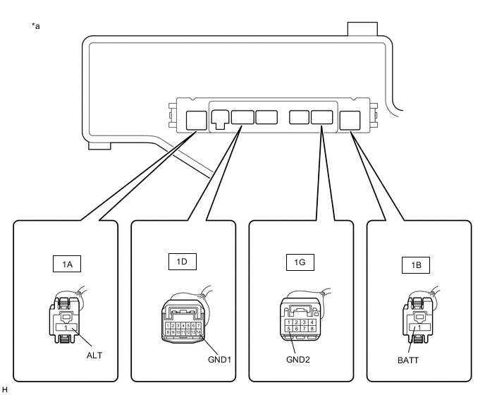
*a Component without semiconductor pwr integration ECU connected
(No. 1 Engine Room Relay Block and No. 1 Junction Block Assembly)
- - -
Measure the voltage according to the value(s) in the table below.
Standard Voltage Tester Connection Condition Specified Condition 1A-1 (ALT) - Body ground Power switch off 11 to 14 V 1B-1 (BATT) - Body ground Power switch off 11 to 14 V -
Measure the resistance according to the value(s) in the table below.
Standard Resistance Tester Connection Condition Specified Condition 1D-14 (GND1) - Body ground Always Below 1 Ω 1G-5 (GND2) - Body ground Always Below 1 Ω Result Proceed to OK NG
NG
REPAIR OR REPLACE HARNESS OR CONNECTOR
OK
-
-
CHECK WIRE HARNESS AND CONNECTOR (SEMICONDUCTOR PWR INTEGRATION ECU - HEATER WATER PUMP ASSEMBLY AND BODY GROUND)
-
Disconnect the A11 heater water pump assembly connector.
-
Measure the resistance according to the value(s) in the table below.
Standard Resistance Tester Connection Condition Specified Condition 1D-12 (L) - A11-2 Always Below 1 Ω 1D-12 (L) - Body ground Always 10 kΩ or higher A11-1 - Body ground Always Below 1 Ω Result Proceed to OK NG
NG
REPAIR OR REPLACE HARNESS OR CONNECTOR
OK
-
-
CHECK WIRE HARNESS AND CONNECTOR (SEMICONDUCTOR PWR INTEGRATION ECU - HYBRID VEHICLE CONTROL ECU ASSEMBLY)
-
Disconnect the A84 hybrid vehicle control ECU assembly connector.
-
Measure the resistance according to the value(s) in the table below.
Standard Resistance Tester Connection Condition Specified Condition 1D-4 (-S) - A84-32 (WP) Always Below 1 Ω 1D-4 (-S) - Body ground Always 10 kΩ or higher Result Proceed to OK NG
NG
REPAIR OR REPLACE HARNESS OR CONNECTOR
OK
-
-
CHECK HEATER WATER PUMP ASSEMBLY
-
Disconnect the A11 heater water pump assembly connector.
-
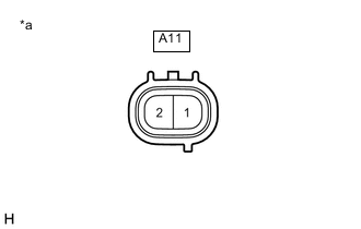
*a Component without harness connected
(Heater Water Pump Assembly)
Connect the auxiliary battery positive (+) lead to terminal 2 of the heater water pump assembly connector and the auxiliary battery negative (-) lead to terminal 1. Then check that the heater water pump assembly operates smoothly.
OK Heater water pump assembly operates smoothly. Note
Complete the check within 10 seconds if there is no water in the heater water pump assembly.
Result Proceed to OK NG
NG
REPLACE HEATER WATER PUMP ASSEMBLY Click here
OK
-
-
CHECK HYBRID VEHICLE CONTROL ECU ASSEMBLY
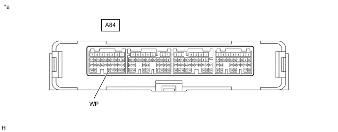
*a Component with harness connected
(Hybrid Vehicle Control ECU Assembly)
- -
-
Reconnect the A84 hybrid vehicle control ECU assembly connector.
-
Remove the hybrid vehicle control ECU assembly with the connectors still connected.
-
Measure the voltage according to the value(s) in the table below.
Standard Voltage Tester Connection Condition Specified Condition A84-32 (WP) - Body ground
-
Power switch on (READY)
-
A/C switch off
11 to 14 V A84-32 (WP) - Body ground
-
Power switch on (READY)
-
A/C switch on
Below 2 V Result Proceed to OK NG -
OK
REPLACE SEMICONDUCTOR PWR INTEGRATION ECU Click here
NG
REPLACE HYBRID VEHICLE CONTROL ECU ASSEMBLY Click here
-