AIR CONDITIONING SYSTEM, Diagnostic DTC:B1476/76
| DTC Code | DTC Name |
|---|---|
| B1476/76 | A/C Inverter Load System Malfunction |
DESCRIPTION
The operation of the compressor with motor assembly is stopped and this DTC is stored if the rotation load is too large or too small while the compressor with motor assembly is operating.
Possible causes are refrigerant leaks, overcharged refrigerant, insufficient cooling due to a condenser fan circuit malfunction, or compressor lock.
| DTC No. | Detection Item | DTC Detection Condition | Trouble Area | Memory |
|---|---|---|---|---|
| B1476/76 | A/C Inverter Load System Malfunction | Motor rotation load while the compressor is operating is too large or too small |
|
Memorized |
CAUTION / NOTICE / HINT
CAUTION:
-
Wear insulated gloves and pull out the service plug grip before inspection as procedures may require disconnecting high-voltage connectors. Carry the removed service plug in your pocket to prevent other technicians from accidentally reconnecting it while you are servicing the vehicle.
-
Do not touch the high-voltage connectors or terminals for 10 minutes after the service plug grip is removed.
Note
-
After turning the power switch off, waiting time may be required before disconnecting the cable from the negative (-) auxiliary battery terminal. Therefore, make sure to read the disconnecting the cable from the negative (-) auxiliary battery terminal notices before proceeding with work.
-
The hybrid control system and air conditioning system output DTCs separately. Perform troubleshooting for the hybrid control system first if DTCs from these systems are output simultaneously.
PROCEDURE
-
CHECK CAN COMMUNICATION SYSTEM
-
Using the GTS, check if the CAN communication system is functioning normally.
Result Result Proceed to CAN communication system DTCs are not output A CAN communication system DTCs are output B
B 
GO TO CAN COMMUNICATION SYSTEM Click here
A 
-
-
PERFORM ACTIVE TEST USING GTS
-
Connect the GTS to the DLC3.
-
Turn the power switch on (IG).
-
Turn the GTS on.
-
Enter the following menus: Powertrain / Engine and ECT / Active Test.
-
Check the operation by referring to the table below.
Powertrain > Engine and ECT > Active TestTester Display Measurement Item Control Range Diagnostic Note Control the Electric Cooling Fan Control electric cooling fan motor ON/OFF Perform this test when the following conditions are met:
-
Power switch on (IG)
-
Engine stopped
-
Shift lever in P
Powertrain > Engine and ECT > Active TestTester Display Control the Electric Cooling Fan Result Proceed to OK NG -
NG
GO TO COOLING FAN SYSTEM Click here
OK
-
-
CHECK REFRIGERANT PRESSURE
-
Install a manifold gauge set.
for HFC-134a (R134a): Click here
for HFO-1234yf (R1234yf): Click here
-
Turn the power switch on (READY).
-
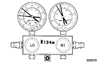
Read the manifold gauge pressure when the following conditions are met.
-
Prepare the vehicle according to the table below.
Item Condition Vehicle doors Fully open Temperature setting MAX COLD Blower speed HI A/C switch On Recirculation/fresh switch RECIRCULATION Interior temperature 25 to 35°C (77 to 95°F)
Standard Pressure Low pressure side 150 to 250 kPa (1.5 to 2.5 kgf/cm2, 22 to 36 psi) High pressure side 1370 to 1570 kPa (14 to 16 kgf/cm2, 199 to 228 psi) Result Result Proceed to OK A NG (for HFC-134a (R134a)) B NG (for HFO-1234yf (R-1234yf)) C -
A
REPLACE COMPRESSOR WITH MOTOR ASSEMBLY Click here
B
CHARGE REFRIGERANT Click here
C
CHARGE REFRIGERANT Click here
-