AIR CONDITIONING SYSTEM, Diagnostic DTC:B1473/73
| DTC Code | DTC Name |
|---|---|
| B1473/73 | A/C Inverter Start-up Signal System Malfunction |
DESCRIPTION
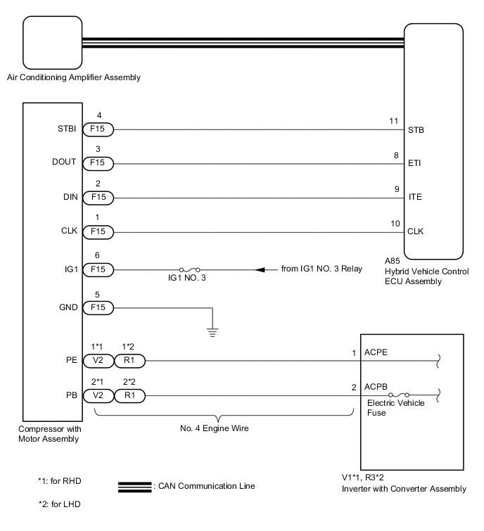
The inverter activation signal is sent to the compressor with motor assembly from the hybrid vehicle control ECU assembly. Compressor control is stopped and this DTC is stored if there is an open or short in the signal circuit.
| DTC No. | Detection Item | DTC Detection Condition | Trouble Area | Memory |
|---|---|---|---|---|
| B1473/73 | A/C Inverter Start-up Signal System Malfunction | Open or short in A/C inverter start-up signal system |
|
- |
WIRING DIAGRAM
CAUTION / NOTICE / HINT
CAUTION:
-
Wear insulated gloves and pull out the service plug grip before inspection as procedures may require disconnecting high-voltage connectors. Carry the removed service plug in your pocket to prevent other technicians from accidentally reconnecting it while you are servicing the vehicle.
-
Do not touch the high-voltage connectors or terminals for 10 minutes after the service plug grip is removed.
Note
-
After turning the power switch off, waiting time may be required before disconnecting the cable from the negative (-) auxiliary battery terminal. Therefore, make sure to read the disconnecting the cable from the negative (-) auxiliary battery terminal notices before proceeding with work.
-
The hybrid control system and air conditioning system output DTCs separately. Perform troubleshooting for the hybrid control system first if DTCs from these systems are output simultaneously.
PROCEDURE
-
CHECK CAN COMMUNICATION SYSTEM
-
Using the GTS, check if the CAN communication system is functioning normally.
Result Result Proceed to CAN communication system DTCs are not output A CAN communication system DTCs are output B
B 
GO TO CAN COMMUNICATION SYSTEM Click here
A 
-
-
CHECK FOR DTC
-
Check if air conditioning system and hybrid control system DTCs are output.
Powertrain > Hybrid Control > Trouble Codes
Body Electrical > Air Conditioner > Trouble CodesResult Result Proceed to Only DTC B1473/73 is output A DTCs B1473/73 and P3108 are output simultaneously (B1498/98 is not output) DTCs B1473/73 and B1498/98 are output simultaneously (P3108 is not output) B DTCs B1473/73, B1498/98 and P3108 are output simultaneously DTCs other than P3108 are output for hybrid control system C
B
GO TO DTC B1498/98 Click here
C
GO TO HYBRID CONTROL SYSTEM Click here
A
-
-
CHECK HARNESS AND CONNECTOR (HYBRID VEHICLE CONTROL ECU ASSEMBLY - COMPRESSOR WITH MOTOR ASSEMBLY)
CAUTION:
Do not disconnect the connector on the high-voltage side.
-
Disconnect the A85 hybrid vehicle control ECU assembly connector.
-
Disconnect the F15 compressor with motor assembly connector.
-
Measure the resistance according to the value(s) in the table below.
Standard Resistance Tester Connection Condition Specified Condition A85-11 (STB) - F15-4 (STBI) Always Below 1 Ω A85-11 (STB) - Body ground Always 10 kΩ or higher Result Proceed to OK NG
NG
REPAIR OR REPLACE HARNESS OR CONNECTOR
OK
-
-
INSPECT COMPRESSOR WITH MOTOR ASSEMBLY
-
Reconnect the F15 compressor with motor assembly connector.
-
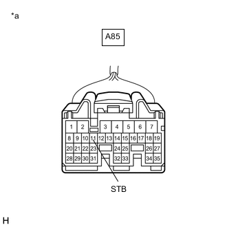
*a Front view of wire harness connector
(to Hybrid Vehicle Control ECU Assembly)
Measure the voltage according to the value(s) in the table below.
Standard Voltage Tester Connection Condition Specified Condition A85-11 (STB) - Body ground Power switch on (IG) 11 to 14 V A85-11 (STB) - Body ground Power switch off Below 1 V Result Proceed to OK NG
OK
REPLACE HYBRID VEHICLE CONTROL ECU ASSEMBLY Click here
NG
REPLACE COMPRESSOR WITH MOTOR ASSEMBLY Click here
-