PRE-COLLISION SYSTEM, Diagnostic DTC:U023A
| DTC Code | DTC Name |
|---|---|
| U023A | Lost Communication with Front Camera Module |
DESCRIPTION
| DTC No. | Detection Item | DTC Detection Condition | Trouble Area |
|---|---|---|---|
| U023A | Lost Communication with Front Camera Module | When the power switch is on (IG), a communication error between the forward recognition camera and driving support ECU is detected for approximately 2 seconds. |
|
WIRING DIAGRAM
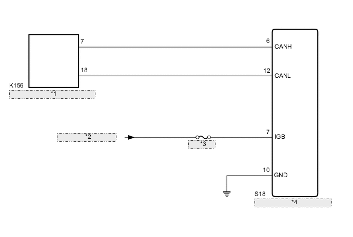
| *1 | No. 21 CAN Junction Connector |
| *2 | from IG1 NO. 3 Relay |
| *3 | IG1 NO. 3 |
| *4 | Forward Recognition Camera |
CAUTION / NOTICE / HINT
Note
-
Inspect the fuses for circuits related to this system before performing the following inspection procedure.
-
Before measuring the resistance of the CAN bus, turn the power switch off and leave the vehicle for 1 minute or more without operating the key or any switches, or opening or closing the doors. After that, disconnect the cable from the negative (-) auxiliary battery terminal and leave the vehicle for 1 minute or more before measuring the resistance.
-
After turning the power switch off, waiting time may be required before disconnecting the cable from the negative (-) auxiliary battery terminal. Therefore, make sure to read the disconnecting the cable from the negative (-) auxiliary battery terminal notices before proceeding with work.
-
When replacing the forward recognition camera, always replace it with a new one. If a forward recognition camera which was installed to another vehicle is used, the information stored in the forward recognition camera will not match the information from the vehicle. As a result, a DTC may be stored.
-
If the forward recognition camera has been replaced with a new one, be sure to perform forward recognition camera adjustment.
Tech Tips
-
Operating the power switch, any other switches or a door triggers related ECU and sensor communication on the CAN. This communication will cause the resistance value to change.
-
Even after DTCs are cleared, if a DTC is stored again after driving the vehicle for a while, the malfunction may be occurring due to vibration of the vehicle. In such a case, wiggling the connectors of ECUs or wire harnesses while performing the inspection below may help determine the cause of the malfunction.
PROCEDURE
-
READ VALUE USING GTS (CAN BUS CHECK)
-
Connect the GTS to the DLC3.
-
Turn the power switch to ON.
-
Turn the GTS on.
-
Enter the following menus: System Select / Can Bus Check.
CAN Bus CheckResult Result Proceed to All of the ECUs and sensors that are currently connected to the CAN communication system are displayed A None of the ECUs and sensors that are currently connected to the CAN communication system are displayed, or some of them are not displayed B
B 
GO TO CAN COMMUNICATION SYSTEM Click here
A 
-
-
CHECK FOR DTCs (PRE-COLLISION SYSTEM)
-
Clear the DTCs.
Body Electrical > Pre-Collision 2 > Clear DTCs -
Perform the following procedure.
Tech Tips
If the following procedure is not performed, the previously output DTC cannot be detected.
-
Turn the power switch on (IG) and wait 2 seconds or more.
-
-
Check for DTCs.
Body Electrical > Pre-Collision 2 > Trouble CodesResult Result Proceed to DTC U1002 is not output A DTC U1002 is output B
B
GO TO DTC CHART (U1002) Click here
A
-
-
CHECK FOR OPEN IN CAN BUS MAIN LINES (FORWARD RECOGNITION CAMERA)
-
Disconnect the cable from the negative (-) auxiliary battery terminal.
-
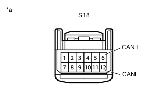
*a Front view of wire harness connector
(to Forward Recognition Camera)
Disconnect the S18 forward recognition camera connector.
-
Measure the resistance according to the value(s) in the table below.
Standard Resistance Tester Connection Condition Specified Condition S18-6 (CANH) - S18-12 (CANL) Cable disconnected from negative (-) auxiliary battery terminal 108 to 132 Ω -
Connect the S18 forward recognition camera connector.
Result Proceed to OK NG
NG
REPAIR OR REPLACE CAN BUS MAIN LINE OR CONNECTOR (NO. 21 CAN JUNCTION CONNECTOR - FORWARD RECOGNITION CAMERA)
OK
-
-
CHECK HARNESS AND CONNECTOR (POWER SOURCE VOLTAGE)
-
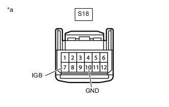
*a Front view of wire harness connector
(to Forward Recognition Camera)
Disconnect the S18 forward recognition camera connector.
-
Measure the resistance according to the value(s) in the table below.
Standard Resistance Tester Connection Condition Specified Condition S18-10 (GND) - Body ground Always Below 1 Ω -
Connect the cable to the negative (-) auxiliary battery terminal.
-
Measure the voltage according to the value(s) in the table below.
Standard Voltage Tester Connection Condition Specified Condition S18-7 (IGB) - Body ground Power switch on (IG) 11 to 14 V -
Connect the S18 forward recognition camera connector.
Result Proceed to OK NG
OK
REPLACE FORWARD RECOGNITION CAMERA Click here
NG
REPAIR OR REPLACE HARNESS OR CONNECTOR (POWER SOURCE CIRCUIT)
-