SIDE AIRBAG SENSOR REMOVAL
CAUTION / NOTICE / HINT
Tech Tips
-
Use the same procedure for the RH side and LH side.
-
The procedure listed below is for the LH side.
PROCEDURE
-
PRECAUTION
Note
After turning the power switch off, waiting time may be required before disconnecting the cable from the negative (-) auxiliary battery terminal. Therefore, make sure to read the disconnecting the cable from the negative (-) auxiliary battery terminal notices before proceeding with work.
-
REMOVE BATTERY SERVICE HOLE COVER LH
-
DISCONNECT CABLE FROM NEGATIVE AUXILIARY BATTERY TERMINAL
CAUTION:
Wait at least 90 seconds after disconnecting the cable from the negative (-) auxiliary battery terminal to disable the SRS system.
Note
When disconnecting the cable, some systems need to be initialized after the cable is reconnected.
-
REMOVE REAR SEAT CUSHION ASSEMBLY
for Fixed Seat Type: Click here
for Fold Down Seat Type: Click here
-
REMOVE REAR SEAT CUSHION LOCK HOOK
for Fixed Seat Type: Click here
for Fold Down Seat Type: Click here
-
REMOVE FRONT DOOR SCUFF PLATE
-
REMOVE REAR DOOR SCUFF PLATE
-
REMOVE LOWER CENTER PILLAR GARNISH
-
REMOVE SIDE AIRBAG SENSOR ASSEMBLY
-
Check that the power switch is off.
-
Check that the cable is disconnected from the negative (-) auxiliary battery terminal.
CAUTION:
Wait at least 90 seconds after disconnecting the cable from the negative (-) auxiliary battery terminal to disable the SRS system.
-
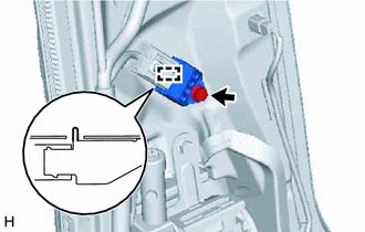
Remove the bolt and separate the side airbag sensor assembly from the vehicle body.
Note
Loosen the bolt while holding the side airbag sensor assembly because the side airbag sensor assembly pin (stopper) is easily damaged.
-
Disconnect the connector to remove the side airbag sensor assembly.
Note
When disconnecting any airbag connector, take care not to damage the airbag wire harness.
-
Push down the white housing lock and slide the yellow CPA. (At this time, the connector cannot be disconnected yet.)
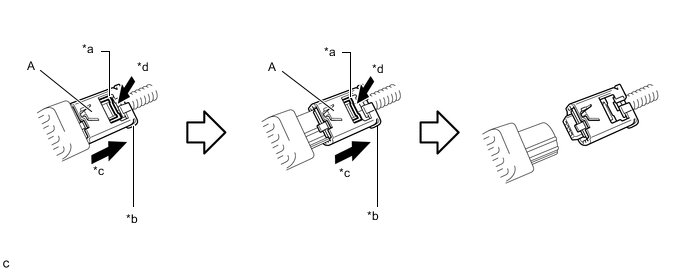
*a White Housing Lock *b Yellow CPA *c Slide *d Push -
Push down the white housing lock again and disconnect the connector.
Note
Do not push down the part (A) shown in the illustration when disconnecting the connector.
-
-
After disconnecting the connector, check that the position of the white housing lock is correct as shown in the illustration.
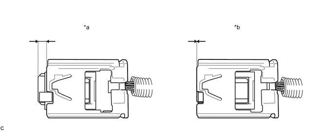
*a Correct *b Incorrect
-