AIRBAG SYSTEM Warning Message on Multi-information Display
DESCRIPTION
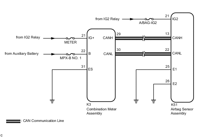
The multi-information display is built into the combination meter assembly.
When there is a malfunction in the pop up hood (including disconnection of a connector) or the pedestrian protection sensors detects a pressure higher than the specified value, the airbag sensor assembly sends a signal via CAN communication to display "POP UP HOOD Failure." on the multi-information display to inform the driver of the malfunction.
The airbag sensor assembly also sends a signal via CAN communication to display "POP UP HOOD Activated." on the multi-information display to inform the driver of pop up hood lifter operation.
If a malfunction occurs in the combination meter assembly, airbag sensor assembly or wire harness connected to the airbag sensor assembly or combination meter assembly, "POP UP HOOD Activated." or "POP UP HOOD Failure." remains displayed on the multi-information display.
WIRING DIAGRAM
CAUTION / NOTICE / HINT
Note
-
After turning the power switch off, waiting time may be required before disconnecting the cable from the negative (-) auxiliary battery terminal. Therefore, make sure to read the disconnecting the cable from the negative (-) auxiliary battery terminal notices before proceeding with work.
-
Inspect the fuses for circuits related to this system before performing the following procedure.
PROCEDURE
-
CHECK MULTI-INFORMATION DISPLAY OPERATION
-
Turn the power switch on (IG) and check the display status of "POP UP HOOD Activated." and "POP UP HOOD Failure.".
Tech Tips
The primary check is performed for approximately 6 seconds after the power switch is turned on (IG).
Result Result Proceed to "POP UP HOOD Activated." or "POP UP HOOD Failure." is displayed immediately after the power switch is turned on (IG). A "POP UP HOOD Activated." or "POP UP HOOD Failure." is displayed when a certain amount of time has elapsed after the power switch is turned on (IG). B
B 
CHECK CAN COMMUNICATION SYSTEM Click here
A 
-
-
CHECK AUXILIARY BATTERY VOLTAGE
-
Measure the voltage of the auxiliary battery.
Standard Voltage 11 to 14 V Result Proceed to OK NG
NG 
INSPECT CHARGING SYSTEM AND AUXILIARY BATTERY Click here
OK
-
-
CHECK CONNECTOR
-
Turn the power switch off.
-
Disconnect the cable from the negative (-) auxiliary battery terminal.
CAUTION:
Wait at least 90 seconds after disconnecting the cable from the negative (-) auxiliary battery terminal to disable the SRS system.
-
Check that the connector is properly connected to the airbag sensor assembly.
OK The connector is properly connected. Tech Tips
If the connector is not properly connected, reconnect the connector and proceed to the next inspection.
-
Disconnect the connector from the airbag sensor assembly.
-
Check that the terminals of the connector are not damaged.
OK The terminals are not deformed or damaged. Result Proceed to OK NG
NG
REPLACE WIRE HARNESS
OK
-
-
CHECK WIRE HARNESS (AIRBAG SENSOR ASSEMBLY - BODY GROUND)
-
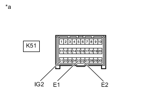
*a Front view of wire harness connector
(to Airbag Sensor Assembly)
Connect the cable to the negative (-) auxiliary battery terminal.
-
Turn the power switch on (IG).
-
Operate all components of the electrical systems (defogger, wipers, headlights, heater blower, etc.).
-
Measure the voltage according to the value(s) in the table below.
Standard Voltage Tester Connection Condition Specified Condition K51-21 (IG2) - Body ground Power switch on (IG) 8 to 16 V -
Turn the power switch off.
-
Measure the resistance according to the value(s) in the table below.
Standard Resistance Tester Connection Condition Specified Condition K51-25 (E1) - Body ground Always Below 1 Ω K51-26 (E2) - Body ground Always Below 1 Ω Result Proceed to OK NG
NG
REPLACE WIRE HARNESS
OK
-
-
CHECK MULTI-INFORMATION DISPLAY
-
Turn the power switch on (IG) and check the display status of the multi-information display.
OK "POP UP HOOD Activated." or "POP UP HOOD Failure." is displayed approximately 10 seconds after the primary check is completed. Tech Tips
The primary check is performed for approximately 6 seconds after the power switch is turned on (IG).
Result Proceed to OK NG
OK
REPLACE AIRBAG SENSOR ASSEMBLY Click here
NG
REPLACE COMBINATION METER ASSEMBLY Click here
-
-
CHECK CAN COMMUNICATION SYSTEM
-
Using the GTS, check if the CAN communication system is functioning normally.
OK CAN communication system is functioning normally. Tech Tips
-
Refer to CAN Bus Check for the CAN communication system.
-
The airbag sensor assembly is connected to the CAN communication system. Therefore, before starting troubleshooting, make sure to check that there are no malfunctions in the CAN communication system.
Result Proceed to OK NG -
NG
GO TO CAN COMMUNICATION SYSTEM Click here
OK
-
-
CHECK AUXILIARY BATTERY VOLTAGE
-
Measure the voltage of the auxiliary battery.
Standard Voltage 11 to 14 V Result Proceed to OK NG
NG
INSPECT CHARGING SYSTEM AND AUXILIARY BATTERY Click here
OK
-
-
CHECK CONNECTOR
-
Turn the power switch off.
-
Disconnect the cable from the negative (-) auxiliary battery terminal.
CAUTION:
Wait at least 90 seconds after disconnecting the cable from the negative (-) auxiliary battery terminal to disable the SRS system.
-
Check that the connector is properly connected to the airbag sensor assembly.
OK The connector is properly connected. Tech Tips
If the connector is not properly connected, reconnect the connector and proceed to the next inspection.
-
Disconnect the connector from the airbag sensor assembly.
-
Check that the terminals of the connector are not damaged.
OK The terminals are not deformed or damaged. Result Proceed to OK NG
NG
REPLACE WIRE HARNESS
OK
-
-
CHECK WIRE HARNESS (AIRBAG SENSOR ASSEMBLY - BODY GROUND)
-
*a Front view of wire harness connector
(to Airbag Sensor Assembly)
Connect the cable to the negative (-) auxiliary battery terminal.
-
Turn the power switch on (IG).
-
Operate all components of the electrical systems (defogger, wipers, headlights, heater blower, etc.).
-
Measure the voltage according to the value(s) in the table below.
Standard Voltage Tester Connection Condition Specified Condition K51-21 (IG2) - Body ground Power switch on (IG) 8 to 16 V -
Turn the power switch off.
-
Measure the resistance according to the value(s) in the table below.
Standard Resistance Tester Connection Condition Specified Condition K51-25 (E1) - Body ground Always Below 1 Ω K51-26 (E2) - Body ground Always Below 1 Ω Result Proceed to OK NG
NG
REPLACE WIRE HARNESS
OK
-
-
CHECK CONNECTOR
-
Disconnect the cable from the negative (-) auxiliary battery terminal.
CAUTION:
Wait at least 90 seconds after disconnecting the cable from the negative (-) auxiliary battery terminal to disable the SRS system.
-
Check that the connector is properly connected to the combination meter assembly.
OK The connector is properly connected. Tech Tips
If the connector is not properly connected, reconnect the connector and proceed to the next inspection.
-
Disconnect the connector from the combination meter assembly.
-
Check that the terminals of the connector are not damaged.
OK The terminals are not deformed or damaged. Result Proceed to OK NG
NG
REPAIR OR REPLACE CONNECTOR
OK
-
-
CHECK WIRE HARNESS (COMBINATION METER ASSEMBLY - BODY GROUND)
-
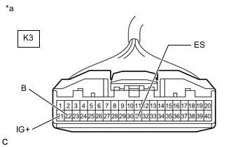
*a Front view of wire harness connector
(to Combination Meter Assembly)
Connect the cable to the negative (-) auxiliary battery terminal.
-
Turn the power switch on (IG).
-
Measure the voltage according to the value(s) in the table below.
Standard Voltage Tester Connection Condition Specified Condition K3-21 (IG+) - Body ground Power switch on (IG) 11 to 14 V K3-22 (B) - Body ground Always 11 to 14 V -
Turn the power switch off.
-
Measure the resistance according to the value(s) in the table below.
Standard Resistance Tester Connection Condition Specified Condition K3-31 (ES) - Body ground Always Below 1 Ω Result Proceed to OK NG
NG
REPAIR OR REPLACE WIRE HARNESS
OK
-
-
CHECK MULTI-INFORMATION DISPLAY
-
Disconnect the cable from the negative (-) auxiliary battery terminal.
CAUTION:
Wait at least 90 seconds after disconnecting the cable from the negative (-) auxiliary battery terminal to disable the SRS system.
-
Connect the connector to the combination meter assembly.
-
Connect the cable to the negative (-) auxiliary battery terminal.
-
Turn the power switch on (IG) and check the display status of the multi-information display.
OK "POP UP HOOD Activated." or "POP UP HOOD Failure." is displayed approximately 10 seconds after the primary check is completed. Tech Tips
The primary check is performed for approximately 6 seconds after the power switch is turned on (IG).
Result Proceed to OK NG
OK
REPLACE AIRBAG SENSOR ASSEMBLY Click here
NG
REPLACE COMBINATION METER ASSEMBLY Click here
-