HOW TO TROUBLESHOOT ECU CONTROLLED SYSTEMS GENERAL INFORMATION
-
A large number of ECU controlled systems are used in this vehicle. In general, ECU controlled systems are considered to be very intricate, requiring a high level of technical knowledge to troubleshoot. However, most problem checking procedures only involve inspecting the ECU controlled system circuits one by one. An adequate understanding of the system and a basic knowledge of electricity is enough to perform effective troubleshooting, accurate diagnosis and necessary repairs.
-
For using the GTS
-
Before using the GTS, read the operator's manual thoroughly.
-
If the GTS cannot communicate with the ECU controlled systems when connected to the DLC3 with the power switch on (IG) and the GTS on, there is a problem on the vehicle side or the GTS side.
-
If communication is possible when the GTS is connected to another vehicle, inspect the diagnosis data link line (bus (+) line), CANH and CANL lines, and the power circuits for the vehicle ECUs.
-
If communication is still not possible when the GTS is connected to another vehicle, the problem is probably in the GTS itself. Perform the Self Test procedure outlined in the GTS operator's manual.
-
TROUBLESHOOTING PROCEDURES
-
The troubleshooting procedures consist of diagnosis procedures for when a DTC is stored and diagnosis procedures for when no DTC is stored. The basic idea is explained in the following table.
Procedure Type Details Troubleshooting Method DTC Based Diagnosis The diagnosis procedure is based on the DTC that is stored. The malfunctioning part is identified based on the DTC detection conditions using a process of elimination.
The possible trouble areas are eliminated one-by-one using the GTS and inspection of related parts.
Symptom Based Diagnosis
(No DTCs stored)
The diagnosis procedure is based on problem symptoms. The malfunctioning part is identified based on the problem symptoms using a process of elimination.
The possible trouble areas are eliminated one-by-one using the GTS and inspection of related parts.
-
Vehicle systems are complex and use many ECUs that are difficult to inspect independently. Therefore, a process of elimination is used, where components that can be inspected individually are inspected, and if no problems are found in these components, the related ECU is identified as the problem and replaced.
-
It is extremely important to ask the customer about the environment and the conditions present when the problem occurred (Customer Problem Analysis). This makes it possible to simulate the conditions and confirm the symptom. If the symptom cannot be confirmed or the DTC does not recur, the malfunctioning part may not be identified using the troubleshooting procedure, and the ECU for the related system may be replaced even though it is not defective. If this happens, the original problem will not be solved.
-
In order to prevent endless expansion of troubleshooting procedures, the troubleshooting procedures are written with the assumption that multiple malfunctions do not occur simultaneously for a single problem symptom.
-
To identify the malfunctioning part, troubleshooting procedures narrow down the target by separating components, ECUs and wire harnesses during the inspection. If the wire harness is identified as the cause of the problem, it is necessary to inspect not only the connections to components and ECUs but also all of the wire harness connectors between the component and the ECU.
-
-
DESCRIPTION
-
The data of each system and Diagnostic Trouble Codes (DTCs) can be read from the Data Link Connector 3 (DLC3) of the vehicle. When the system seems to be malfunctioning, use the GTS to check for malfunctions and perform repairs.
-
-
CHECK DLC3
-
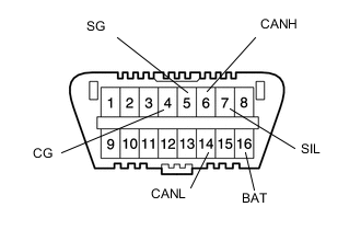
The vehicle ECUs use ISO 15765-4 communication protocol. The terminal arrangement of the DLC3 complies with ISO 15031-3 and matches the ISO 15765-4 format.
Symbol Terminal No. Name Reference Terminal Result Condition SIL 7 Bus "+" line 5 - Signal ground Pulse generation During transmission CG 4 Chassis ground Body ground 1 Ω or less Always SG 5 Signal ground Body ground 1 Ω or less Always BAT 16 Auxiliary battery positive Body ground 11 to 14 V Power switch off CANH 6 CAN "High" line 14 - CANL 54 to 69 Ω Power switch off* Auxiliary battery positive 6 kΩ or higher Power switch off* 4 - CG 200 Ω or higher Power switch off* CANL 14 CAN "Low" line Auxiliary battery positive 6 kΩ or higher Power switch off* 4 - CG 200 Ω or higher Power switch off* Note
*: Before measuring the resistance, leave the vehicle as is for at least 1 minute and do not operate the power switch, any other switches or the doors.
If the result is not as specified, the DLC3 may be a malfunctioning. Repair or replace the harness or connector.
-