WIPER AND WASHER SYSTEM TERMINALS OF ECU
-
CHECK WINDSHIELD WIPER SWITCH ASSEMBLY
-
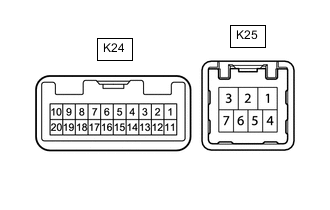
Disconnect the K24 and K25 windshield wiper switch assembly connectors.
-
Measure the voltage and resistance on the wire harness side connector according to the value(s) in the table below.
Terminal No.
(Symbol)
Wiring Color Terminal Description Condition Specified Condition K24-2 (+B) - Body ground R - Body ground Engine switch on (IG) signal (Power source circuit) Engine switch on (IG) 11 to 14 V Engine switch off Below 1 V K24-3 (TAIL) - Body ground*1 LG - Body ground Headlight dimmer switch position signal Engine switch on (IG) 11 to 14 V Engine switch off Below 1 V K24-4 (RLY2) - Body ground R - Body ground INT relay operation signal Engine switch on (IG) 11 to 14 V Engine switch off Below 1 V K24-5 (RLY1) - Body ground B - Body ground WIP relay operation signal Engine switch on (IG) 11 to 14 V Engine switch off Below 1 V K24-7 (E) - Body ground BR - Body ground Ground Always Below 1 Ω K25-4 (EW) - Body ground*2 W-B - Body ground Ground Always Below 1 Ω K25-7 (EW) - Body ground*3 W-B - Body ground Ground Always Below 1 Ω
-
*1: w/ Auto Wiper System
-
*2: for LHD, RHD (for Wiper Switch RH Side Type)
-
*3: for RHD (for Wiper Switch LH Side Type)
Tech Tips
If the result is not as specified, there may be a malfunction in the wire harness.
-
-
Reconnect the K24 and K25 windshield wiper switch assembly connectors.
-
Measure the voltage and check for pulses according to the value(s) in the table below.
Terminal No.
(Symbol)
Wiring Color Terminal Description Condition Specified Condition K24-3 (TAIL) - Body ground*1 LG - Body ground Headlight dimmer switch position signal Engine switch on (IG), headlight dimmer switch in off position 11 to 14 V Engine switch on (IG), headlight dimmer switch in on position Below 1 V K24-4 (RLY2) - Body ground R - Body ground INT relay operation signal Engine switch on (IG), wiper switch off 11 to 14 V Engine switch on (IG), wiper switch in HI position Below 1 V K24-5 (RLY1) - Body ground B - Body ground WIP relay operation signal Engine switch on (IG), wiper switch off 11 to 14 V Engine switch on (IG), wiper switch in LO position Below 1 V K24-8 (MPX1) - Body ground*1 G - Body ground LIN communication signal Engine switch on (IG) Pulse generation K24-10 (CSS+) - K24-9 (CSS-) R - L Vehicle speed signal Engine switch on (IG), wheel being rotated Pulse generation K24-20 (+S) - Body ground G - Body ground Wiper motor operation signal Engine switch on (IG), wiper switch off 11 to 14 V Engine switch on (IG), wiper switch in LO or HI position Below 1 V K25-4 (WF) - Body ground*2 R - Body ground Washer motor operation signal Engine switch on (IG), washer switch off 11 to 14 V Engine switch on (IG), washer switch on Below 1 V K25-7 (WF) - Body ground*3 R - Body ground Washer motor operation signal Engine switch on (IG), washer switch off 11 to 14 V Engine switch on (IG), washer switch on Below 1 V
-
*1: w/ Auto Wiper System
-
*2: for RHD (for Wiper Switch LH Side Type)
-
*3: for LHD, RHD (for Wiper Switch RH Side Type)
Tech Tips
If the result is not as specified, the windshield wiper switch assembly may be malfunctioning.
-
-
-
CHECK HEADLIGHT CLEANER CONTROL RELAY (w/ Headlight Cleaner System)
-
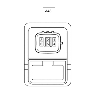
Disconnect the A48 headlight cleaner control relay connector.
-
Measure the voltage and resistance on the wire harness side connector according to the value(s) in the table below.
Terminal No.
(Symbol)
Wiring Color Terminal Description Condition Specified Condition A48-3 (IG) - Body ground B - Body ground Engine switch on (IG) signal (Power source circuit) Engine switch on (IG) 11 to 14 V Engine switch off Below 1 V A48-4 (E) - Body ground W-B - Body ground Ground Always Below 1 Ω A48-6 (PB) - Body ground W - Body ground Headlight cleaner motor operation signal Always 11 to 14 V Tech Tips
If the result is not as specified, there may be a malfunction in the wire harness.
-
-
CHECK NO. 1 HEADLIGHT ECU SUB-ASSEMBLY RH (w/ Headlight Cleaner System)
-
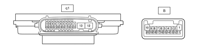
Measure the voltage according to the value(s) in the table below.
Terminal No.
(Symbol)
Wiring Color Terminal Description Condition Specified Condition q1-18 (FRWA) - Body ground R - Body ground Washer switch operation signal Engine switch on (IG), washer switch off 5 V Engine switch on (IG), washer switch on Below 1 V q1-7 (HLC) - Body ground R - Body ground Headlight cleaner operation signal Engine switch on (IG), headlight cleaner not operating 11 to 14 V Engine switch on (IG), headlight cleaner operating Below 1 V Tech Tips
If the result is not as specified, the headlight leveling ECU assembly may be malfunctioning.
-