CAN COMMUNICATION SYSTEM Open in Bus 2 Main Bus Line
DESCRIPTION
There may be an open circuit in one of the CAN main bus lines and/or a central gateway ECU (network gateway ECU) branch lines when the resistance between terminals 18 (CA4H) and 17 (CA4L) of the central gateway ECU (network gateway ECU) is 70 Ω or higher.
| Symptom | Trouble Area |
|---|---|
| Resistance between terminals 18 (CA4H) and 17 (CA4L) of central gateway ECU (network gateway ECU) is 70 Ω or higher. |
|
This malfunction is not related to the lines of a CAN branch except the central gateway ECU (network gateway ECU) branch lines or to ECUs or sensors connected to a CAN branch.
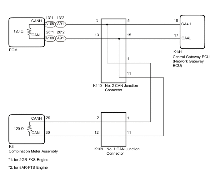
WIRING DIAGRAM
Figure 1. for LHD:
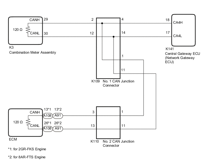
Figure 2. for RHD:
CAUTION / NOTICE / HINT
CAUTION:
When performing the confirmation driving pattern, obey all speed limits and traffic laws.
Note
-
Because the order of diagnosis is important to allow correct diagnosis, make sure to begin troubleshooting using How to Proceed with Troubleshooting when CAN communication system related DTCs are output.
-
Before measuring the resistance of the CAN bus, turn the engine switch off and leave the vehicle for 1 minute or more without operating the key or any switches, or opening or closing the doors. After that, disconnect the cable from the negative (-) battery terminal and leave the vehicle for 1 minute or more before measuring the resistance.
-
After turning the engine switch off, waiting time may be required before disconnecting the cable from the negative (-) battery terminal. Therefore, make sure to read the disconnecting the cable from the negative (-) battery terminal notices before proceeding with work.
-
After performing repairs, perform the DTC check procedure and confirm that the DTCs are not output again.
DTC check procedure: Turn the ignition switch to ON and wait for 1 minute or more. Then operate the suspected malfunctioning system and drive the vehicle at 60 km/h (37 mph) or more for 5 minutes or more.
-
After the repair, perform the CAN bus check and check that all the ECUs and sensors connected to the CAN communication system are displayed as normal.
-
Before replacing the ECM, refer to Service Bulletin.
Tech Tips
-
Before disconnecting related connectors for inspection, push in on each connector body to check that the connector is not loose or disconnected.
-
When a connector is disconnected, check that the terminals and connector body are not cracked, deformed or corroded.
PROCEDURE
-
CHECK FOR OPEN IN CAN BUS LINES (CENTRAL GATEWAY ECU (NETWORK GATEWAY ECU) BRANCH LINES)
-
Disconnect the cable from the negative (-) battery terminal.
-
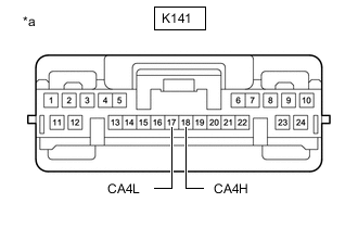
*a Front view of wire harness connector
(to Central Gateway ECU (Network Gateway ECU))
Disconnect the K141 central gateway ECU (network gateway ECU) connector.
-
Measure the resistance according to the value(s) in the table below.
Standard Resistance Tester Connection Condition Specified Condition K141-18 (CA4H) - K141-17 (CA4L) Cable disconnected from negative (-) battery terminal 108 to 132 Ω Result Result OK NG
NG 
REPAIR OR REPLACE CAN BRANCH LINES OR CONNECTOR (CENTRAL GATEWAY ECU (NETWORK GATEWAY ECU))
OK 
-
-
CHECK FOR OPEN IN CAN BUS LINES (COMBINATION METER ASSEMBLY)
-
Reconnect the K141 central gateway ECU (network gateway ECU) connector.
-
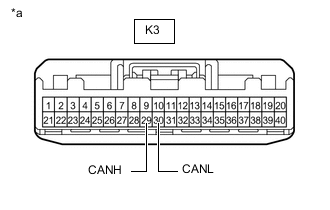
*a Front view of wire harness connector
(to Combination Meter Assembly)
Disconnect the K3 combination meter assembly connector.
-
Measure the resistance according to the value(s) in the table below.
Standard Resistance Tester Connection Condition Specified Condition K3-29 (CANH) - K3-30 (CANL) Cable disconnected from negative (-) battery terminal 108 to 132 Ω Result Result Proceed to OK A NG (for 2GR-FKS Engine) B NG (for 8AR-FTS Engine) C
A
REPLACE COMBINATION METER ASSEMBLY Click here
C 
CHECK FOR OPEN IN CAN BUS LINES (ECM) Click here
B
-
-
CHECK FOR OPEN IN CAN BUS LINES (ECM)
-
Reconnect the K3 combination meter assembly connector.
-
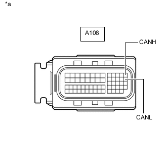
*a Front view of wire harness connector
(to ECM)
Disconnect the A108 ECM connector.
-
Measure the resistance according to the value(s) in the table below.
Standard Resistance Tester Connection Condition Specified Condition A108-13 (CANH) - A108-26 (CANL) Cable disconnected from negative (-) battery terminal 108 to 132 Ω Result Result OK NG
OK
REPLACE ECM Click here
NG
GO TO STEP 5 Click here
-
-
CHECK FOR OPEN IN CAN BUS LINES (ECM)
-
Reconnect the K3 combination meter assembly connector.
-
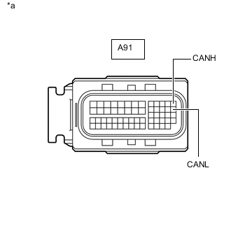
*a Front view of wire harness connector
(to ECM)
Disconnect the A91 ECM connector.
-
Measure the resistance according to the value(s) in the table below.
Standard Resistance Tester Connection Condition Specified Condition A91-13 (CANH) - A91-26 (CANL) Cable disconnected from negative (-) battery terminal 108 to 132 Ω Result Result OK NG
OK
REPLACE ECM Click here
NG
-
-
CHECK FOR OPEN IN CAN BUS LINES (NO. 1 CAN JUNCTION CONNECTOR)
-
Reconnect the A108*1 or A91*2 ECM connector.
-
*1: for 2GR-FKS Engine
-
*2: for 8AR-FTS Engine
-
-
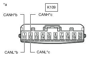
*a Front view of wire harness connector
(to No. 1 CAN Junction Connector)
*b to No. 2 CAN Junction Connector *c to Combination Meter Assembly Disconnect the K109 No. 1 CAN junction connector.
-
Measure the resistance according to the value(s) in the table below.
Standard Resistance Tester Connection Condition Specified Condition Connected to K109-1 (CANH) - K109-11 (CANL) Cable disconnected from negative (-) battery terminal 108 to 132 Ω No. 2 CAN junction connector K109-2 (CANH) - K109-12 (CANL) Cable disconnected from negative (-) battery terminal 108 to 132 Ω Combination meter assembly Result Result Proceed to OK A NG (Line to No. 2 CAN junction connector) B NG (Line to combination meter assembly) C
A
REPLACE NO. 1 CAN JUNCTION CONNECTOR
C
REPAIR OR REPLACE CAN MAIN BUS LINES OR CONNECTOR (COMBINATION METER ASSEMBLY - NO. 1 CAN JUNCTION CONNECTOR)
B
-
-
CHECK FOR OPEN IN CAN BUS LINES (NO. 2 CAN JUNCTION CONNECTOR)
-
Reconnect the K109 No. 1 CAN junction connector.
-
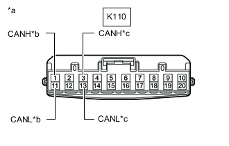
*a Front view of wire harness connector
(to No. 2 CAN Junction Connector)
*b to No. 1 CAN Junction Connector *c to ECM Disconnect the K110 No. 2 CAN junction connector.
-
Measure the resistance according to the value(s) in the table below.
Standard Resistance Tester Connection Condition Specified Condition Connected to K110-1 (CANH) - K110-11 (CANL) Cable disconnected from negative (-) battery terminal 108 to 132 Ω No. 1 CAN junction connector K110-3 (CANH) - K110-13 (CANL) Cable disconnected from negative (-) battery terminal 108 to 132 Ω ECM Result Result Proceed to OK A NG (Line to No. 1 CAN junction connector) B NG (Line to ECM) C
A
REPLACE NO. 2 CAN JUNCTION CONNECTOR
B
REPAIR OR REPLACE CAN MAIN BUS LINES OR CONNECTOR (NO. 1 CAN JUNCTION CONNECTOR - NO. 2 CAN JUNCTION CONNECTOR)
C
REPAIR OR REPLACE CAN MAIN BUS LINES OR CONNECTOR (ECM - NO. 2 CAN JUNCTION CONNECTOR)
-