CAN COMMUNICATION SYSTEM Check Bus 5 Line for Short to GND
DESCRIPTION
There may be a short circuit between one of the CAN bus lines and GND when there is no resistance between terminal 15 (CA5H) of the central gateway ECU (network gateway ECU) and terminal 4 (CG) of the DLC3, or terminal 16 (CA5L) of the central gateway ECU (network gateway ECU) and terminal 4 (CG) of the DLC3.
| Symptom | Trouble Area |
|---|---|
| No resistance exists between terminal 15 (CA5H) of the central gateway ECU (network gateway ECU) and terminal 4 (CG) of the DLC3, or terminal 16 (CA5L) of the central gateway ECU (network gateway ECU) and terminal 4 (CG) of the DLC3. |
|
WIRING DIAGRAM
Figure 1. for LHD:
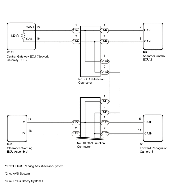
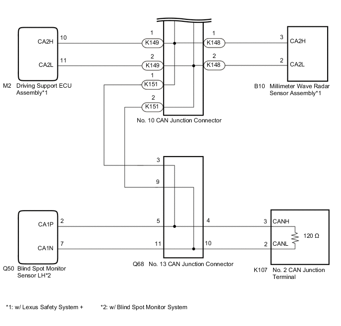
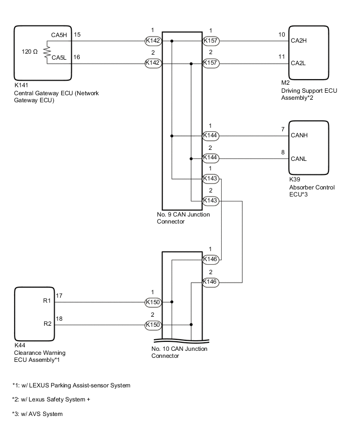
Figure 2. for RHD:

CAUTION / NOTICE / HINT
CAUTION:
When performing the confirmation driving pattern, obey all speed limits and traffic laws.
Note
-
Because the order of diagnosis is important to allow correct diagnosis, make sure to begin troubleshooting using How to Proceed with Troubleshooting when CAN communication system related DTCs are output.
-
Before measuring the resistance of the CAN bus, turn the engine switch off and leave the vehicle for 1 minute or more without operating the key or any switches, or opening or closing the doors. After that, disconnect the cable from the negative (-) battery terminal and leave the vehicle for 1 minute or more before measuring the resistance.
-
After turning the engine switch off, waiting time may be required before disconnecting the cable from the negative (-) battery terminal. Therefore, make sure to read the disconnecting the cable from the negative (-) battery terminal notices before proceeding with work.
-
After performing repairs, perform the DTC check procedure and confirm that the DTCs are not output again.
DTC check procedure: Turn the ignition switch to ON and wait for 1 minute or more. Then operate the suspected malfunctioning system and drive the vehicle at 60 km/h (37 mph) or more for 5 minutes or more.
-
After the repair, perform the CAN bus check and check that all the ECUs and sensors connected to the CAN communication system are displayed as normal.
-
Before replacing the main body ECU (multiplex network body ECU) or certification ECU (smart key ECU assembly), refer to Service Bulletin.
Tech Tips
-
Before disconnecting related connectors for inspection, push in on each connector body to check that the connector is not loose or disconnected.
-
When a connector is disconnected, check that the terminals and connector body are not cracked, deformed or corroded.
PROCEDURE
-
CHECK VEHICLE TYPE
-
Check vehicle type.
Result Result Proceed to for LHD A for RHD B
B 
CHECK FOR SHORT TO GND IN CAN BUS LINE (NO. 10 CAN JUNCTION CONNECTOR) Click here
A 
-
-
CHECK FOR SHORT TO GND IN CAN BUS LINE (NO. 10 CAN JUNCTION CONNECTOR)
-
Disconnect the cable from the negative (-) battery terminal.
-
Disconnect the K146, K147, K148, K149, K150 and K151 No. 10 CAN junction connectors.
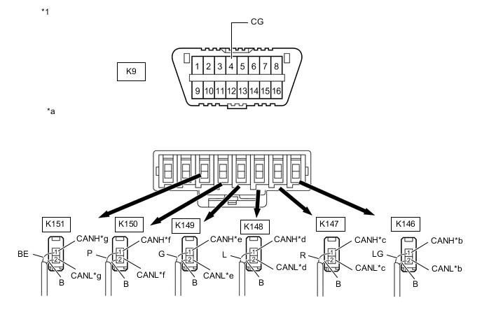
*1 DLC3 - - *a Rear view of wire harness connector
(to No. 10 CAN Junction Connector)
*b to No. 9 CAN Junction Connector *c to Forward Recognition Camera
(w/ Lexus Safety System +)
*d to Millimeter Wave Radar Sensor Assembly
(w/ Lexus Safety System +)
*e to Driving Support ECU Assembly
(w/ Lexus Safety System +)
*f to Clearance Warning ECU Assembly
(w/ LEXUS Parking Assist-sensor System)
*g to No. 13 CAN Junction Connector - - Wiring Color: Code Color (CANH Side) Color (CANL Side) Connected to K146 LG B No. 9 CAN junction connector K147 R B Forward recognition camera K148 L B Millimeter wave radar sensor assembly K149 G B Driving support ECU assembly K150 P B Clearance warning ECU assembly K151 BE B No. 13 CAN junction connector -
Measure the resistance according to the value(s) in the table below.
Standard Resistance Tester Connection Condition Specified Condition Connected to K146-1 (CANH) - K9-4 (CG) Cable disconnected from negative (-) battery terminal 200 Ω or higher No. 9 CAN junction connector K146-2 (CANL) - K9-4 (CG) K147-1 (CANH) - K9-4 (CG) Cable disconnected from negative (-) battery terminal 200 Ω or higher Forward recognition camera*1 K147-2 (CANL) - K9-4 (CG) K148-1 (CANH) - K9-4 (CG) Cable disconnected from negative (-) battery terminal 200 Ω or higher Millimeter wave radar sensor assembly*1 K148-2 (CANL) - K9-4 (CG) K149-1 (CANH) - K9-4 (CG) Cable disconnected from negative (-) battery terminal 200 Ω or higher Driving support ECU assembly*1 K149-2 (CANL) - K9-4 (CG) K150-1 (CANH) - K9-4 (CG) Cable disconnected from negative (-) battery terminal 200 Ω or higher Clearance warning ECU assembly*2 K150-2 (CANL) - K9-4 (CG) K151-1 (CANH) - K9-4 (CG) Cable disconnected from negative (-) battery terminal 200 Ω or higher No. 13 CAN junction connector K151-2 (CANL) - K9-4 (CG)
-
*1: w/ Lexus Safety System +
-
*2: w/ LEXUS Parking Assist-sensor System
Result Result Proceed to OK A NG (Line to No. 9 CAN junction connector) B NG (Line to No. 13 CAN junction connector) C NG (Line to ECU or sensor) D -
A 
REPLACE NO. 10 CAN JUNCTION CONNECTOR
C
CHECK FOR SHORT TO GND IN CAN BUS LINE (NO. 13 CAN JUNCTION CONNECTOR) Click here
D
GO TO STEP 11 Click here
B
-
-
CHECK FOR SHORT TO GND IN CAN BUS LINE (NO. 9 CAN JUNCTION CONNECTOR)
-
Reconnect the K146, K147, K148, K149, K150 and K151 No. 10 CAN junction connectors.
-
Disconnect the K142, K143 and K144 No. 9 CAN junction connectors.
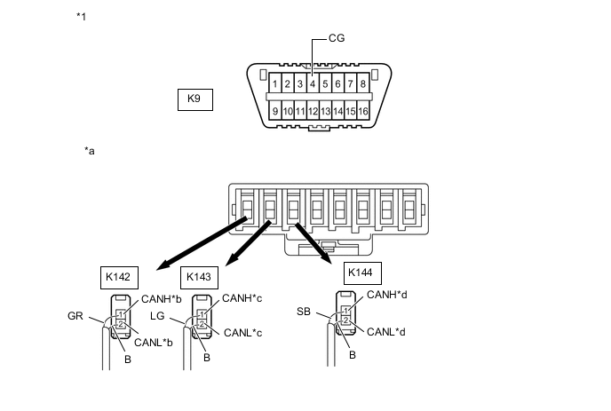
*1 DLC3 - - *a Rear view of wire harness connector
(to No. 9 CAN Junction Connector)
*b to Central Gateway ECU (Network Gateway ECU) *c to No. 10 CAN Junction Connector *d to Absorber Control ECU
(w/ AVS System)
Wiring Color: Code Color (CANH Side) Color (CANL Side) Connected to K142 GR B Central gateway ECU (network gateway ECU) K143 LG B No. 10 CAN junction connector K144 SB B Absorber control ECU -
Measure the resistance according to the value(s) in the table below.
Standard Resistance Tester Connection Condition Specified Condition Connected to K142-1 (CANH) - K9-4 (CG) Cable disconnected from negative (-) battery terminal 200 Ω or higher Central gateway ECU (network gateway ECU) K142-2 (CANL) - K9-4 (CG) K143-1 (CANH) - K9-4 (CG) Cable disconnected from negative (-) battery terminal 200 Ω or higher No. 10 CAN junction connector K143-2 (CANL) - K9-4 (CG) K144-1 (CANH) - K9-4 (CG) Cable disconnected from negative (-) battery terminal 200 Ω or higher Absorber control ECU* K144-2 (CANL) - K9-4 (CG)
-
*: w/ AVS System
Result Result Proceed to OK A NG (Line to central gateway ECU (network gateway ECU)) B NG (Line to No. 10 CAN junction connector) C NG (Line to ECU or sensor) D -
A
REPLACE NO. 9 CAN JUNCTION CONNECTOR
C
REPAIR OR REPLACE CAN MAIN BUS LINE OR CONNECTOR (NO. 9 CAN JUNCTION CONNECTOR - NO. 10 CAN JUNCTION CONNECTOR)
D
GO TO STEP 11 Click here
B
-
-
CHECK FOR SHORT TO GND IN CAN BUS LINE (CENTRAL GATEWAY ECU (NETWORK GATEWAY ECU))
-
Reconnect the K142, K143 and K144 No. 9 CAN junction connectors.
-
Disconnect the K141 central gateway ECU (network gateway ECU) connector.
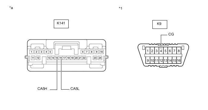
*1 DLC3 - - *a Front view of wire harness connector
(to Central Gateway ECU (Network Gateway ECU))
- - -
Measure the resistance according to the value(s) in the table below.
Standard Resistance Tester Connection Condition Specified Condition K141-15 (CA5H) - K9-4 (CG) Cable disconnected from negative (-) battery terminal 200 Ω or higher K141-16 (CA5L) - K9-4 (CG) Result Result OK NG
OK
REPLACE CENTRAL GATEWAY ECU (NETWORK GATEWAY ECU) Click here
NG
REPAIR OR REPLACE CAN MAIN BUS LINE OR CONNECTOR (CENTRAL GATEWAY ECU (NETWORK GATEWAY ECU) - NO. 9 CAN JUNCTION CONNECTOR)
-
-
CHECK FOR SHORT TO GND IN CAN BUS LINE (NO. 13 CAN JUNCTION CONNECTOR)
-
Reconnect the K146, K147, K148, K149, K150 and K151 No. 10 CAN junction connectors.
-
Disconnect the Q68 No. 13 CAN junction connector.
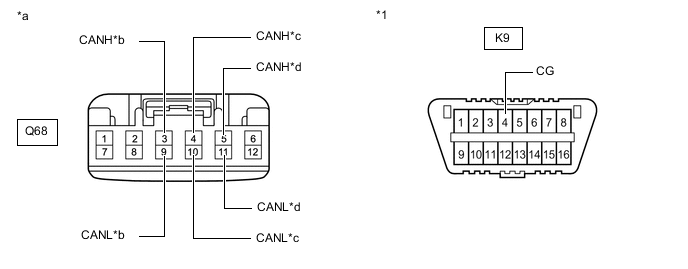
*1 DLC3 - - *a Front view of wire harness connector
(to No. 13 CAN Junction Connector)
*b to No. 10 CAN Junction Connector *c to No. 2 CAN Junction Terminal *d to Blind Spot Monitor Sensor LH
(w/ Blind Spot Monitor System)
-
Measure the resistance according to the value(s) in the table below.
Standard Resistance Tester Connection Condition Specified Condition Connected to Q68-3 (CANH) - K9-4 (CG) Cable disconnected from negative (-) battery terminal 200 Ω or higher No. 10 CAN junction connector Q68-9 (CANL) - K9-4 (CG) Q68-4 (CANH) - K9-4 (CG) Cable disconnected from negative (-) battery terminal 200 Ω or higher No. 2 CAN junction terminal Q68-10 (CANL) - K9-4 (CG) Q68-5 (CANH) - K9-4 (CG) Cable disconnected from negative (-) battery terminal 200 Ω or higher Blind spot monitor sensor LH* Q68-11 (CANL) - K9-4 (CG)
-
*: w/ Blind Spot Monitor System
Result Result Proceed to OK A NG (Line to No. 10 CAN junction connector) B NG (Line to No. 2 CAN junction terminal) C NG (Line to ECU or sensor) D -
A
REPLACE NO. 13 CAN JUNCTION CONNECTOR
B
REPAIR OR REPLACE CAN MAIN BUS LINE OR CONNECTOR (NO. 10 CAN JUNCTION CONNECTOR - NO. 13 CAN JUNCTION CONNECTOR)
C
GO TO STEP 10 Click here
D
GO TO STEP 11 Click here
-
-
CHECK FOR SHORT TO GND IN CAN BUS LINE (NO. 10 CAN JUNCTION CONNECTOR)
-
Disconnect the cable from the negative (-) battery terminal.
-
Disconnect the K146, K147, K148, K150 and K151 No. 10 CAN junction connectors.
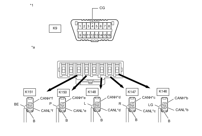
*1 DLC3 - - *a Rear view of wire harness connector
(to No. 10 CAN Junction Connector)
*b to No. 9 CAN Junction Connector *c to Forward Recognition Camera
(w/ Lexus Safety System +)
*d to Millimeter Wave Radar Sensor Assembly
(w/ Lexus Safety System +)
*e to Clearance Warning ECU Assembly
(w/ LEXUS Parking Assist-sensor System)
*f to No. 13 CAN Junction Connector Wiring Color: Code Color (CANH Side) Color (CANL Side) Connected to K146 LG B No. 9 CAN junction connector K147 R B Forward recognition camera K148 L B Millimeter wave radar sensor assembly K150 P B Clearance warning ECU assembly K151 BE B No. 13 CAN junction connector -
Measure the resistance according to the value(s) in the table below.
Standard Resistance Tester Connection Condition Specified Condition Connected to K146-1 (CANH) - K9-4 (CG) Cable disconnected from negative (-) battery terminal 200 Ω or higher No. 9 CAN junction connector K146-2 (CANL) - K9-4 (CG) K147-1 (CANH) - K9-4 (CG) Cable disconnected from negative (-) battery terminal 200 Ω or higher Forward recognition camera*1 K147-2 (CANL) - K9-4 (CG) K148-1 (CANH) - K9-4 (CG) Cable disconnected from negative (-) battery terminal 200 Ω or higher Millimeter wave radar sensor assembly*1 K148-2 (CANL) - K9-4 (CG) K150-1 (CANH) - K9-4 (CG) Cable disconnected from negative (-) battery terminal 200 Ω or higher Clearance warning ECU assembly*2 K150-2 (CANL) - K9-4 (CG) K151-1 (CANH) - K9-4 (CG) Cable disconnected from negative (-) battery terminal 200 Ω or higher No. 13 CAN junction connector K151-2 (CANL) - K9-4 (CG)
-
*1: w/ Lexus Safety System +
-
*2: w/ LEXUS Parking Assist-sensor System
Result Result Proceed to OK A NG (Line to No. 9 CAN junction connector) B NG (Line to No. 13 CAN junction connector) C NG (Line to ECU or sensor) D -
A
REPLACE NO. 10 CAN JUNCTION CONNECTOR
C
CHECK FOR SHORT TO GND IN CAN BUS LINE (NO. 13 CAN JUNCTION CONNECTOR) Click here
D
GO TO STEP 11 Click here
B
-
-
CHECK FOR SHORT TO GND IN CAN BUS LINE (NO. 9 CAN JUNCTION CONNECTOR)
-
Reconnect the K146, K147, K148, K150 and K151 No. 10 CAN junction connectors.
-
Disconnect the K142, K143 K144 and K157 No. 9 CAN junction connectors.
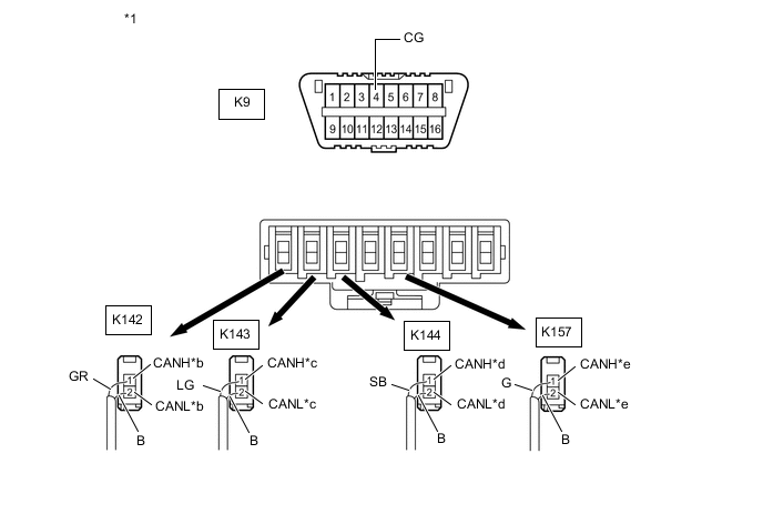
*1 DLC3 - - *a Rear view of wire harness connector
(to No. 9 CAN Junction Connector)
*b to Central Gateway ECU (Network Gateway ECU) *c to No. 10 CAN Junction Connector *d to Absorber Control ECU
(w/ AVS System)
*e to Driving Support ECU Assembly
(w/ Lexus Safety System +)
- - Wiring Color: Code Color (CANH Side) Color (CANL Side) Connected to K142 GR B Central gateway ECU (network gateway ECU) K143 LG B No. 10 CAN junction connector K144 SB B Absorber control ECU K157 G B Driving support ECU assembly -
Measure the resistance according to the value(s) in the table below.
Standard Resistance Tester Connection Condition Specified Condition Connected to K142-1 (CANH) - K9-4 (CG) Cable disconnected from negative (-) battery terminal 200 Ω or higher Central gateway ECU (network gateway ECU) K142-2 (CANL) - K9-4 (CG) K143-1 (CANH) - K9-4 (CG) Cable disconnected from negative (-) battery terminal 200 Ω or higher No. 10 CAN junction connector K143-2 (CANL) - K9-4 (CG) K144-1 (CANH) - K9-4 (CG) Cable disconnected from negative (-) battery terminal 200 Ω or higher Absorber control ECU*1 K144-2 (CANL) - K9-4 (CG) K157-1 (CANH) - K9-4 (CG) Cable disconnected from negative (-) battery terminal 200 Ω or higher Driving support ECU assembly*2 K157-2 (CANL) - K9-4 (CG)
-
*1: w/ AVS System
-
*2: w/ Lexus Safety System +
Result Result Proceed to OK A NG (Line to central gateway ECU (network gateway ECU)) B NG (Line to No. 10 CAN junction connector) C NG (Line to ECU or sensor) D -
A
REPLACE NO. 9 CAN JUNCTION CONNECTOR
C
REPAIR OR REPLACE CAN MAIN BUS LINE OR CONNECTOR (NO. 9 CAN JUNCTION CONNECTOR - NO. 10 CAN JUNCTION CONNECTOR)
D
GO TO STEP 11 Click here
B
-
-
CHECK FOR SHORT TO GND IN CAN BUS LINE (CENTRAL GATEWAY ECU (NETWORK GATEWAY ECU))
-
Reconnect the K142, K143 K144 and K157 No. 9 CAN junction connectors.
-
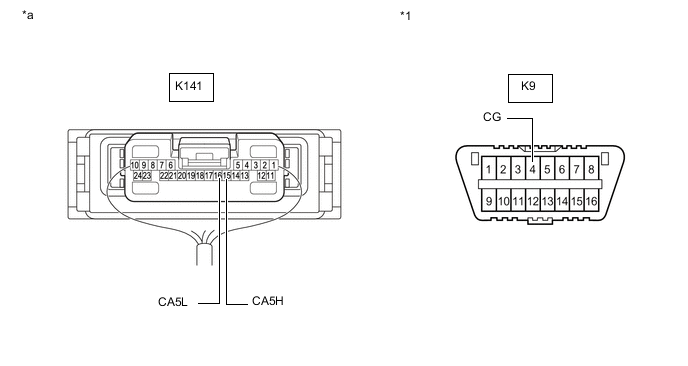
Disconnect the K141 central gateway ECU (network gateway ECU) connector.
*1 DLC3 - - *a Front view of wire harness connector
(to Central Gateway ECU (Network Gateway ECU))
- - -
Measure the resistance according to the value(s) in the table below.
Standard Resistance Tester Connection Condition Specified Condition K141-15 (CA5H) - K9-4 (CG) Cable disconnected from negative (-) battery terminal 200 Ω or higher K141-16 (CA5L) - K9-4 (CG) Result Result OK NG
OK
REPLACE CENTRAL GATEWAY ECU (NETWORK GATEWAY ECU) Click here
NG
REPAIR OR REPLACE CAN MAIN BUS LINE OR CONNECTOR (CENTRAL GATEWAY ECU (NETWORK GATEWAY ECU) - NO. 9 CAN JUNCTION CONNECTOR)
-
-
CHECK FOR SHORT TO GND IN CAN BUS LINE (NO. 13 CAN JUNCTION CONNECTOR)
-
Reconnect the K146, K147, K148, K150 and K151 No. 10 CAN junction connectors.
-
Disconnect the Q68 No. 13 CAN junction connector.
*1 DLC3 - - *a Front view of wire harness connector
(to No. 13 CAN Junction Connector)
*b to No. 10 CAN Junction Connector *c to No. 2 CAN Junction Terminal *d to Blind Spot Monitor Sensor LH
(w/ Blind Spot Monitor System)
-
Measure the resistance according to the value(s) in the table below.
Standard Resistance Tester Connection Condition Specified Condition Connected to Q68-3 (CANH) - K9-4 (CG) Cable disconnected from negative (-) battery terminal 200 Ω or higher No. 10 CAN junction connector Q68-9 (CANL) - K9-4 (CG) Q68-4 (CANH) - K9-4 (CG) Cable disconnected from negative (-) battery terminal 200 Ω or higher No. 2 CAN junction terminal Q68-10 (CANL) - K9-4 (CG) Q68-5 (CANH) - K9-4 (CG) Cable disconnected from negative (-) battery terminal 200 Ω or higher Blind spot monitor sensor LH* Q68-11 (CANL) - K9-4 (CG)
-
*: w/ Blind Spot Monitor System
Result Result Proceed to OK A NG (Line to No. 10 CAN junction connector) B NG (Line to No. 2 CAN junction terminal) C NG (Line to ECU or sensor) D -
A
REPLACE NO. 13 CAN JUNCTION CONNECTOR
B
REPAIR OR REPLACE CAN MAIN BUS LINE OR CONNECTOR (NO. 10 CAN JUNCTION CONNECTOR - NO. 13 CAN JUNCTION CONNECTOR)
D
CHECK FOR SHORT TO GND IN CAN BUS LINE (ECU, SENSOR) Click here
C
-
-
CHECK FOR SHORT TO GND IN CAN BUS LINE (NO. 2 CAN JUNCTION TERMINAL)
-
Reconnect the Q68 No. 13 CAN junction connector.
-
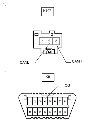
*1 DLC3 *a Front view of wire harness connector
(to No. 2 CAN Junction Terminal)
Disconnect the K107 No. 2 CAN junction terminal connector.
-
Measure the resistance according to the value(s) in the table below.
Standard Resistance Tester Connection Condition Specified Condition K107-3 (CANH) - K9-4 (CG) Cable disconnected from negative (-) battery terminal 200 Ω or higher K107-2 (CANL) - K9-4 (CG) Result Result OK NG
OK
REPLACE NO. 2 CAN JUNCTION TERMINAL
NG
REPAIR OR REPLACE CAN MAIN BUS LINE OR CONNECTOR (NO. 2 CAN JUNCTION TERMINAL - NO. 13 CAN JUNCTION CONNECTOR)
-
-
CHECK FOR SHORT TO GND IN CAN BUS LINE (ECU, SENSOR)
-
Reconnect all wire harness connectors.
-
Disconnect the connector that includes terminals CANH and CANL from the ECU or sensor to which the bus line shorted to GND is connected.
-
Measure the resistance according to the value(s) in the table below.
*1 DLC3 - - *a Component with harness connected
(Central Gateway ECU (Network Gateway ECU))
- - Standard Resistance Tester Connection Condition Specified Condition K141-15 (CA5H) - K9-4 (CG) Cable disconnected from negative (-) battery terminal 200 Ω or higher K141-16 (CA5L) - K9-4 (CG) Tech Tips
If the resistance changes to 200 Ω or higher when the connector is disconnected from the ECU or sensor, there may be a short in the ECU or sensor.
Result Result OK NG
OK
REPLACE CORRESPONDING ECU OR SENSOR
NG
REPAIR OR REPLACE CORRESPONDING ECU OR SENSOR CAN BUS LINE OR CONNECTOR
-