CAN COMMUNICATION SYSTEM Check Bus 5 Line for Short to GND
DESCRIPTION
There may be a short circuit between one of the CAN bus lines and GND when there is no resistance between terminal 15 (CA5H) of the central gateway ECU (network gateway ECU) and terminal 4 (CG) of the DLC3, or terminal 16 (CA5L) of the central gateway ECU (network gateway ECU) and terminal 4 (CG) of the DLC3.
| Symptom | Trouble Area |
|---|---|
| No resistance exists between terminal 15 (CA5H) of the central gateway ECU (network gateway ECU) and terminal 4 (CG) of the DLC3, or terminal 16 (CA5L) of the central gateway ECU (network gateway ECU) and terminal 4 (CG) of the DLC3. |
|
WIRING DIAGRAM
Figure 1. for LHD w/ No. 11 CAN Junction Connector:

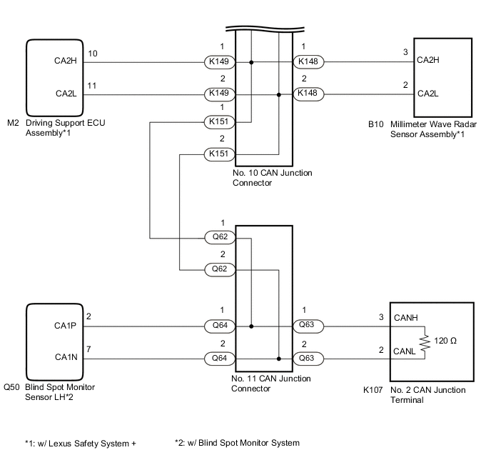
Figure 2. for LHD w/ No. 13 CAN Junction Connector:
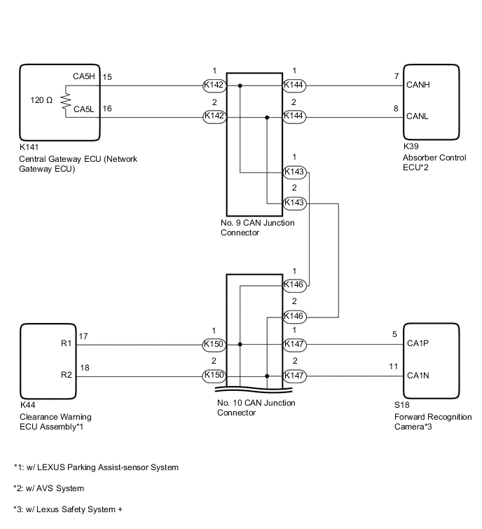

Figure 3. for RHD w/ No. 11 CAN Junction Connector:
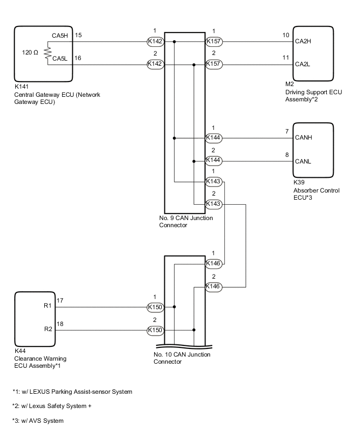
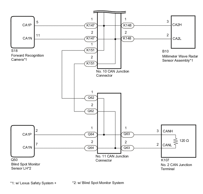
Figure 4. for RHD w/ No. 13 CAN Junction Connector:

CAUTION / NOTICE / HINT
Note
-
Because the order of diagnosis is important to allow correct diagnosis, make sure to begin troubleshooting using How to Proceed with Troubleshooting when CAN communication system related DTCs are output.
-
Before measuring the resistance of the CAN bus, turn the engine switch off and leave the vehicle for 1 minute or more without operating the key or any switches, or opening or closing the doors. After that, disconnect the cable from the negative (-) battery terminal and leave the vehicle for 1 minute or more before measuring the resistance.
-
After turning the engine switch off, waiting time may be required before disconnecting the cable from the negative (-) battery terminal. Therefore, make sure to read the disconnecting the cable from the negative (-) battery terminal notices before proceeding with work.
-
After performing repairs, perform the DTC check procedure and confirm that the DTCs are not output again.
DTC check procedure: Turn the engine switch on (IG) and wait at least 20 seconds, turn the lane departure alert system on using the LDA main switch, turn the dynamic radar cruise control system on using the cruise control main switch, and then drive the vehicle at a speed of 40 km/h (25 mph) or more for 52 seconds or more.
-
After the repair, perform the CAN bus check and check that all the ECUs and sensors connected to the CAN communication system are displayed as normal.
-
Before replacing the main body ECU (multiplex network body ECU) or certification ECU (smart key ECU assembly), refer to Service Bulletin.
Tech Tips
-
Before disconnecting related connectors for inspection, push in on each connector body to check that the connector is not loose or disconnected.
-
When a connector is disconnected, check that the terminals and connector body are not cracked, deformed or corroded.
PROCEDURE
-
CHECK VEHICLE TYPE
-
Check vehicle type.
Result Result Proceed to for LHD A for RHD B
B 
CHECK FOR SHORT TO GND IN CAN BUS LINE (NO. 10 CAN JUNCTION CONNECTOR) Click here
A 
-
-
CHECK FOR SHORT TO GND IN CAN BUS LINE (NO. 10 CAN JUNCTION CONNECTOR)
-
Disconnect the cable from the negative (-) battery terminal.
-
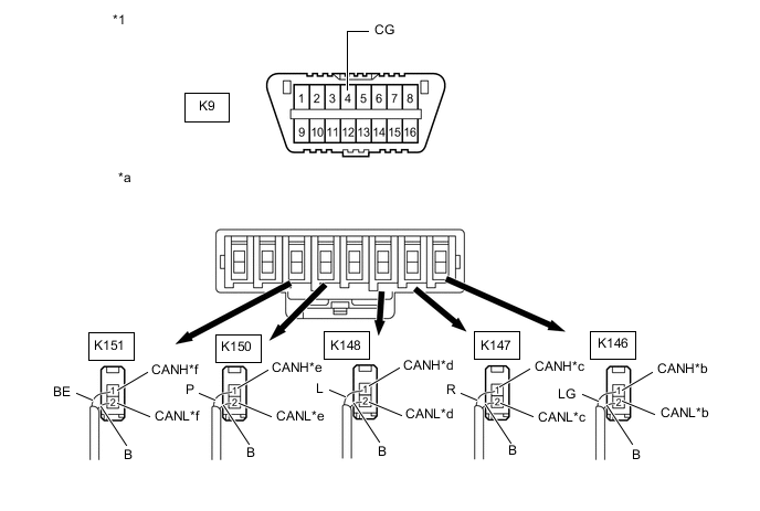
Disconnect the K146, K147, K148, K149, K150 and K151 No. 10 CAN junction connectors.
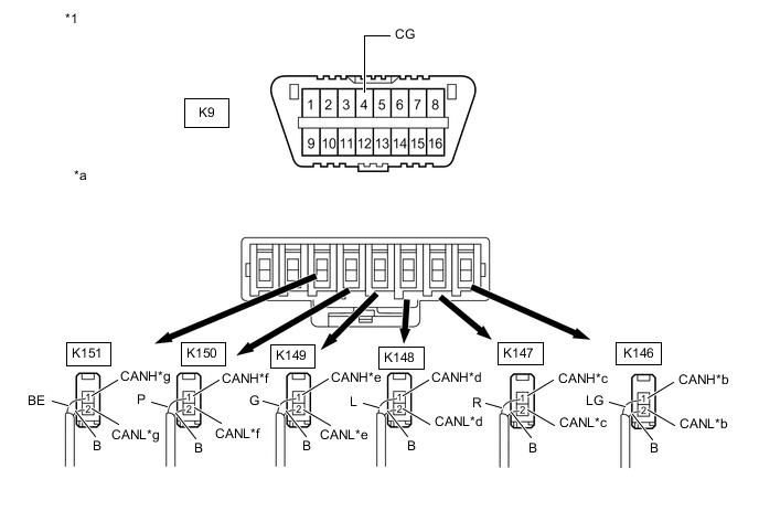
*1 DLC3 - - *a Rear view of wire harness connector
(to No. 10 CAN Junction Connector)
*b to No. 9 CAN Junction Connector *c to Forward Recognition Camera
(w/ Lexus Safety System +)
*d to Millimeter Wave Radar Sensor Assembly
(w/ Lexus Safety System +)
*e to Driving Support ECU Assembly
(w/ Lexus Safety System +)
*f to Clearance Warning ECU Assembly
(w/ LEXUS Parking Assist-sensor System)
*g to No. 11 CAN Junction Connector or No. 13 CAN Junction Connector - - Wiring Color: Code Color (CANH Side) Color (CANL Side) Connected to K146 LG B No. 9 CAN junction connector K147 R B Forward recognition camera K148 L B Millimeter wave radar sensor assembly K149 G B Driving support ECU assembly K150 P B Clearance warning ECU assembly K151 BE B No. 11 CAN junction connector or No. 13 CAN junction connector -
Measure the resistance according to the value(s) in the table below.
Standard Resistance Tester Connection Condition Specified Condition Connected to K146-1 (CANH) - K9-4 (CG) Cable disconnected from negative (-) battery terminal 200 Ω or higher No. 9 CAN junction connector K146-2 (CANL) - K9-4 (CG) K147-1 (CANH) - K9-4 (CG) Cable disconnected from negative (-) battery terminal 200 Ω or higher Forward recognition camera*1 K147-2 (CANL) - K9-4 (CG) K148-1 (CANH) - K9-4 (CG) Cable disconnected from negative (-) battery terminal 200 Ω or higher Millimeter wave radar sensor assembly*1 K148-2 (CANL) - K9-4 (CG) K149-1 (CANH) - K9-4 (CG) Cable disconnected from negative (-) battery terminal 200 Ω or higher Driving support ECU assembly*1 K149-2 (CANL) - K9-4 (CG) K150-1 (CANH) - K9-4 (CG) Cable disconnected from negative (-) battery terminal 200 Ω or higher Clearance warning ECU assembly*2 K150-2 (CANL) - K9-4 (CG) K151-1 (CANH) - K9-4 (CG) Cable disconnected from negative (-) battery terminal 200 Ω or higher No. 11 CAN junction connector or No. 13 CAN junction connector K151-2 (CANL) - K9-4 (CG)
-
*1: w/ Lexus Safety System +
-
*2: w/ LEXUS Parking Assist-sensor System
Result Result Proceed to OK A NG (Line to No. 9 CAN junction connector) B NG (Line to No. 11 CAN junction connector or No. 13 CAN junction connector) C NG (Line to ECU or sensor) D -
A 
REPLACE NO. 10 CAN JUNCTION CONNECTOR
C
GO TO STEP 8 Click here
D
GO TO STEP 12 Click here
B
-
-
CHECK FOR SHORT TO GND IN CAN BUS LINE (NO. 9 CAN JUNCTION CONNECTOR)
-
Reconnect the K146, K147, K148, K149, K150 and K151 No. 10 CAN junction connectors.
-
Disconnect the K142, K143 and K144 No. 9 CAN junction connectors.
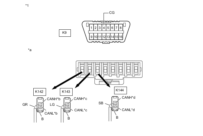
*1 DLC3 - - *a Rear view of wire harness connector
(to No. 9 CAN Junction Connector)
*b to Central Gateway ECU (Network Gateway ECU) *c to No. 10 CAN Junction Connector *d to Absorber Control ECU
(w/ AVS System)
Wiring Color: Code Color (CANH Side) Color (CANL Side) Connected to K142 GR B Central gateway ECU (network gateway ECU) K143 LG B No. 10 CAN junction connector K144 SB B Absorber control ECU -
Measure the resistance according to the value(s) in the table below.
Standard Resistance Tester Connection Condition Specified Condition Connected to K142-1 (CANH) - K9-4 (CG) Cable disconnected from negative (-) battery terminal 200 Ω or higher Central gateway ECU (network gateway ECU) K142-2 (CANL) - K9-4 (CG) K143-1 (CANH) - K9-4 (CG) Cable disconnected from negative (-) battery terminal 200 Ω or higher No. 10 CAN junction connector K143-2 (CANL) - K9-4 (CG) K144-1 (CANH) - K9-4 (CG) Cable disconnected from negative (-) battery terminal 200 Ω or higher Absorber control ECU* K144-2 (CANL) - K9-4 (CG)
-
*: w/ AVS System
Result Result Proceed to OK A NG (Line to central gateway ECU (network gateway ECU)) B NG (Line to No. 10 CAN junction connector) C NG (Line to ECU or sensor) D -
A
REPLACE NO. 9 CAN JUNCTION CONNECTOR
C
REPAIR OR REPLACE CAN MAIN BUS LINE OR CONNECTOR (NO. 9 CAN JUNCTION CONNECTOR - NO. 10 CAN JUNCTION CONNECTOR)
D
GO TO STEP 12 Click here
B
-
-
CHECK FOR SHORT TO GND IN CAN BUS LINE (CENTRAL GATEWAY ECU (NETWORK GATEWAY ECU))
-
Reconnect the K142, K143 and K144 No. 9 CAN junction connectors.
-
Disconnect the K141 central gateway ECU (network gateway ECU) connector.
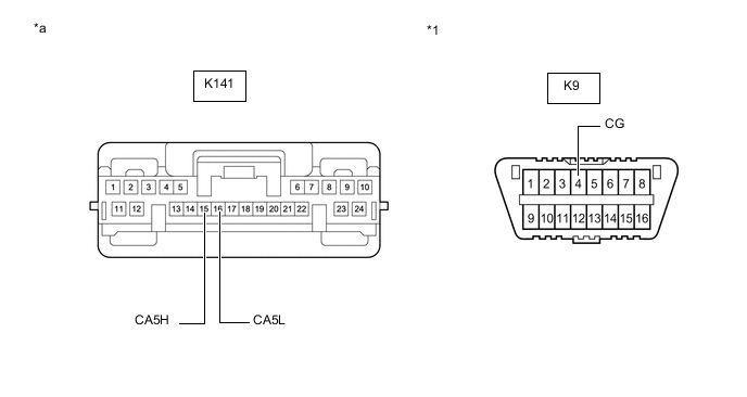
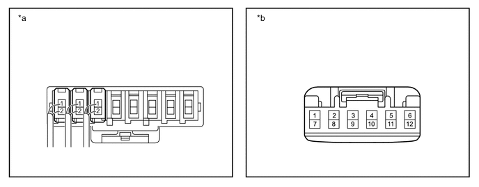
*1 DLC3 - - *a Front view of wire harness connector
(to Central Gateway ECU (Network Gateway ECU))
- - -
Measure the resistance according to the value(s) in the table below.
Standard Resistance Tester Connection Condition Specified Condition K141-15 (CA5H) - K9-4 (CG) Cable disconnected from negative (-) battery terminal 200 Ω or higher K141-16 (CA5L) - K9-4 (CG) Result Result OK NG
OK
REPLACE CENTRAL GATEWAY ECU (NETWORK GATEWAY ECU) Click here
NG
REPAIR OR REPLACE CAN MAIN BUS LINE OR CONNECTOR (CENTRAL GATEWAY ECU (NETWORK GATEWAY ECU) - NO. 9 CAN JUNCTION CONNECTOR)
-
-
CHECK FOR SHORT TO GND IN CAN BUS LINE (NO. 10 CAN JUNCTION CONNECTOR)
-
Disconnect the cable from the negative (-) battery terminal.
-
Disconnect the K146, K147, K148, K150 and K151 No. 10 CAN junction connectors.
*1 DLC3 - - *a Rear view of wire harness connector
(to No. 10 CAN Junction Connector)
*b to No. 9 CAN Junction Connector *c to Forward Recognition Camera
(w/ Lexus Safety System +)
*d to Millimeter Wave Radar Sensor Assembly
(w/ Lexus Safety System +)
*e to Clearance Warning ECU Assembly
(w/ LEXUS Parking Assist-sensor System)
*f to No. 11 CAN Junction Connector or No. 13 CAN Junction Connector Wiring Color: Code Color (CANH Side) Color (CANL Side) Connected to K146 LG B No. 9 CAN junction connector K147 R B Forward recognition camera K148 L B Millimeter wave radar sensor assembly K150 P B Clearance warning ECU assembly K151 BE B No. 11 CAN junction connector or No. 13 CAN junction connector -
Measure the resistance according to the value(s) in the table below.
Standard Resistance Tester Connection Condition Specified Condition Connected to K146-1 (CANH) - K9-4 (CG) Cable disconnected from negative (-) battery terminal 200 Ω or higher No. 9 CAN junction connector K146-2 (CANL) - K9-4 (CG) K147-1 (CANH) - K9-4 (CG) Cable disconnected from negative (-) battery terminal 200 Ω or higher Forward recognition camera*1 K147-2 (CANL) - K9-4 (CG) K148-1 (CANH) - K9-4 (CG) Cable disconnected from negative (-) battery terminal 200 Ω or higher Millimeter wave radar sensor assembly*1 K148-2 (CANL) - K9-4 (CG) K150-1 (CANH) - K9-4 (CG) Cable disconnected from negative (-) battery terminal 200 Ω or higher Clearance warning ECU assembly*2 K150-2 (CANL) - K9-4 (CG) K151-1 (CANH) - K9-4 (CG) Cable disconnected from negative (-) battery terminal 200 Ω or higher No. 11 CAN junction connector or No. 13 CAN junction connector K151-2 (CANL) - K9-4 (CG)
-
*1: w/ Lexus Safety System +
-
*2: w/ LEXUS Parking Assist-sensor System
Result Result Proceed to OK A NG (Line to No. 9 CAN junction connector) B NG (Line to No. 11 CAN junction connector or No. 13 CAN junction connector) C NG (Line to ECU or sensor) D -
A
REPLACE NO. 10 CAN JUNCTION CONNECTOR
C
CHECK VEHICLE TYPE Click here
D
GO TO STEP 12 Click here
B
-
-
CHECK FOR SHORT TO GND IN CAN BUS LINE (NO. 9 CAN JUNCTION CONNECTOR)
-
Reconnect the K146, K147, K148, K150 and K151 No. 10 CAN junction connectors.
-
Disconnect the K142, K143 K144 and K157 No. 9 CAN junction connectors.
*1 DLC3 - - *a Rear view of wire harness connector
(to No. 9 CAN Junction Connector)
*b to Central Gateway ECU (Network Gateway ECU) *c to No. 10 CAN Junction Connector *d to Absorber Control ECU
(w/ AVS System)
*e to Driving Support ECU Assembly
(w/ Lexus Safety System +)
- - Wiring Color: Code Color (CANH Side) Color (CANL Side) Connected to K142 GR B Central gateway ECU (network gateway ECU) K143 LG B No. 10 CAN junction connector K144 SB B Absorber control ECU K157 G B Driving support ECU assembly -
Measure the resistance according to the value(s) in the table below.
Standard Resistance Tester Connection Condition Specified Condition Connected to K142-1 (CANH) - K9-4 (CG) Cable disconnected from negative (-) battery terminal 200 Ω or higher Central gateway ECU (network gateway ECU) K142-2 (CANL) - K9-4 (CG) K143-1 (CANH) - K9-4 (CG) Cable disconnected from negative (-) battery terminal 200 Ω or higher No. 10 CAN junction connector K143-2 (CANL) - K9-4 (CG) K144-1 (CANH) - K9-4 (CG) Cable disconnected from negative (-) battery terminal 200 Ω or higher Absorber control ECU*1 K144-2 (CANL) - K9-4 (CG) K157-1 (CANH) - K9-4 (CG) Cable disconnected from negative (-) battery terminal 200 Ω or higher Driving support ECU assembly*2 K157-2 (CANL) - K9-4 (CG)
-
*1: w/ AVS System
-
*2: w/ Lexus Safety System +
Result Result Proceed to OK A NG (Line to central gateway ECU (network gateway ECU)) B NG (Line to No. 10 CAN junction connector) C NG (Line to ECU or sensor) D -
A
REPLACE NO. 9 CAN JUNCTION CONNECTOR
C
REPAIR OR REPLACE CAN MAIN BUS LINE OR CONNECTOR (NO. 9 CAN JUNCTION CONNECTOR - NO. 10 CAN JUNCTION CONNECTOR)
D
GO TO STEP 12 Click here
B
-
-
CHECK FOR SHORT TO GND IN CAN BUS LINE (CENTRAL GATEWAY ECU (NETWORK GATEWAY ECU))
-
Reconnect the K142, K143 K144 and K157 No. 9 CAN junction connectors.
-
Disconnect the K141 central gateway ECU (network gateway ECU) connector.
*1 DLC3 - - *a Front view of wire harness connector
(to Central Gateway ECU (Network Gateway ECU))
- - -
Measure the resistance according to the value(s) in the table below.
Standard Resistance Tester Connection Condition Specified Condition K141-15 (CA5H) - K9-4 (CG) Cable disconnected from negative (-) battery terminal 200 Ω or higher K141-16 (CA5L) - K9-4 (CG) Result Result OK NG
OK
REPLACE CENTRAL GATEWAY ECU (NETWORK GATEWAY ECU) Click here
NG
REPAIR OR REPLACE CAN MAIN BUS LINE OR CONNECTOR (CENTRAL GATEWAY ECU (NETWORK GATEWAY ECU) - NO. 9 CAN JUNCTION CONNECTOR)
-
-
CHECK VEHICLE TYPE
-
Reconnect all wire harness connectors.
-
Check whether the No. 11 CAN junction connector or No. 13 CAN junction connector is installed to the vehicle.
*a Component with harness connected
(No. 11 CAN Junction Connector)
*b Front view of wire harness connector
(to No. 13 CAN Junction Connector)
Result Result Proceed to w/ No. 11 CAN Junction Connector A w/ No. 13 CAN Junction Connector B
B
CHECK FOR SHORT TO GND IN CAN BUS LINE (NO. 13 CAN JUNCTION CONNECTOR) Click here
A
-
-
CHECK FOR SHORT TO GND IN CAN BUS LINE (NO. 11 CAN JUNCTION CONNECTOR)
-
Disconnect the Q62, Q63 and Q64 No. 11 CAN junction connectors.
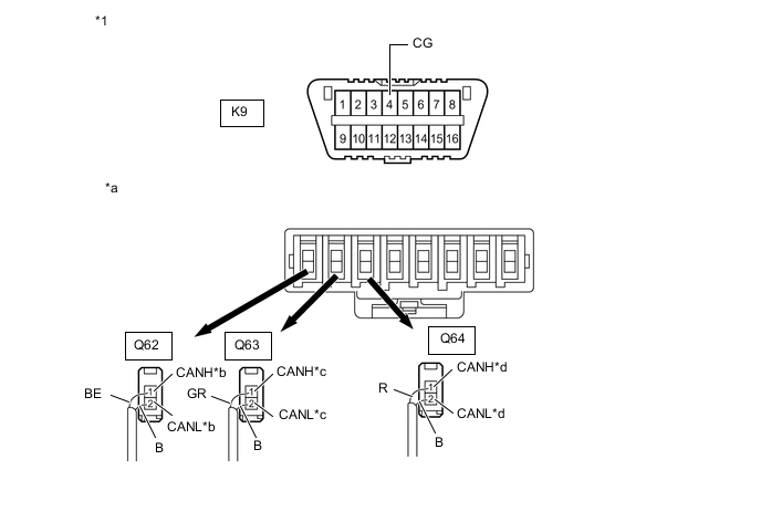
*1 DLC3 - - *a Rear view of wire harness connector
(to No. 11 CAN Junction Connector)
*b to No. 10 CAN Junction Connector *c to No. 2 CAN Junction Terminal *d to Blind Spot Monitor Sensor LH
(w/ Blind Spot Monitor System)
Wiring Color: Code Color (CANH Side) Color (CANL Side) Connected to Q62 BE B No. 10 CAN junction connector Q63 GR B No. 2 CAN junction terminal Q64 R B Blind spot monitor sensor LH -
Measure the resistance according to the value(s) in the table below.
Standard Resistance Tester Connection Condition Specified Condition Connected to Q62-1 (CANH) - K9-4 (CG) Cable disconnected from negative (-) battery terminal 200 Ω or higher No. 10 CAN junction connector Q62-2 (CANL) - K9-4 (CG) Q63-1 (CANH) - K9-4 (CG) Cable disconnected from negative (-) battery terminal 200 Ω or higher No. 2 CAN junction terminal Q63-2 (CANL) - K9-4 (CG) Q64-1 (CANH) - K9-4 (CG) Cable disconnected from negative (-) battery terminal 200 Ω or higher Blind spot monitor sensor LH* Q64-2 (CANL) - K9-4 (CG)
-
*: w/ Blind Spot Monitor System
Result Result Proceed to OK A NG (Line to No. 10 CAN junction connector) B NG (Line to No. 2 CAN junction terminal) C NG (Line to ECU or sensor) D -
A
REPLACE NO. 11 CAN JUNCTION CONNECTOR
B
REPAIR OR REPLACE CAN MAIN BUS LINE OR CONNECTOR (NO. 10 CAN JUNCTION CONNECTOR - NO. 11 CAN JUNCTION CONNECTOR)
C
GO TO STEP 11 Click here
D
GO TO STEP 12 Click here
-
-
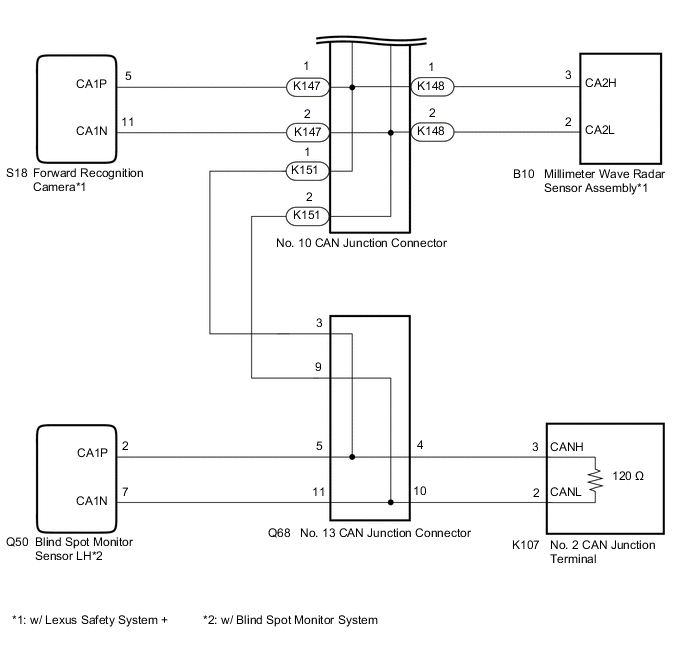
CHECK FOR SHORT TO GND IN CAN BUS LINE (NO. 13 CAN JUNCTION CONNECTOR)
-
Disconnect the Q68 No. 13 CAN junction connector.
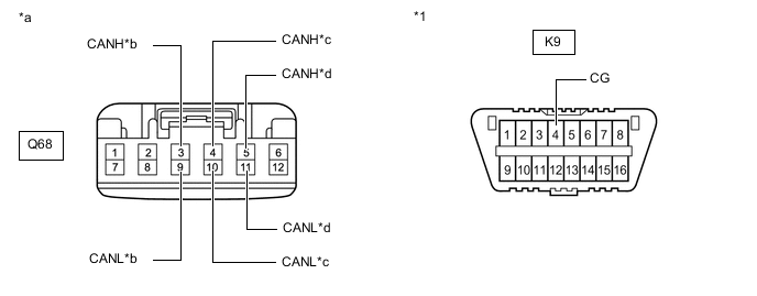
*1 DLC3 - - *a Front view of wire harness connector
(to No. 13 CAN Junction Connector)
*b to No. 10 CAN Junction Connector *c to No. 2 CAN Junction Terminal *d to Blind Spot Monitor Sensor LH
(w/ Blind Spot Monitor System)
-
Measure the resistance according to the value(s) in the table below.
Standard Resistance Tester Connection Condition Specified Condition Connected to Q68-3 (CANH) - K9-4 (CG) Cable disconnected from negative (-) battery terminal 200 Ω or higher No. 10 CAN junction connector Q68-9 (CANL) - K9-4 (CG) Q68-4 (CANH) - K9-4 (CG) Cable disconnected from negative (-) battery terminal 200 Ω or higher No. 2 CAN junction terminal Q68-10 (CANL) - K9-4 (CG) Q68-5 (CANH) - K9-4 (CG) Cable disconnected from negative (-) battery terminal 200 Ω or higher Blind spot monitor sensor LH* Q68-11 (CANL) - K9-4 (CG)
-
*: w/ Blind Spot Monitor System
Result Result Proceed to OK A NG (Line to No. 10 CAN junction connector) B NG (Line to No. 2 CAN junction terminal) C NG (Line to ECU or sensor) D -
A
REPLACE NO. 13 CAN JUNCTION CONNECTOR
B
REPAIR OR REPLACE CAN MAIN BUS LINE OR CONNECTOR (NO. 10 CAN JUNCTION CONNECTOR - NO. 13 CAN JUNCTION CONNECTOR)
D
CHECK FOR SHORT TO GND IN CAN BUS LINE (ECU, SENSOR) Click here
C
-
-
CHECK FOR SHORT TO GND IN CAN BUS LINE (NO. 2 CAN JUNCTION TERMINAL)
-
Reconnect all wire harness connectors.
-
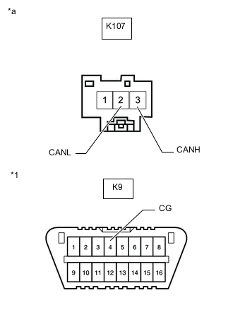
*1 DLC3 *a Front view of wire harness connector
(to No. 2 CAN Junction Terminal)
Disconnect the K107 No. 2 CAN junction terminal connector.
-
Measure the resistance according to the value(s) in the table below.
Standard Resistance Tester Connection Condition Specified Condition K107-3 (CANH) - K9-4 (CG) Cable disconnected from negative (-) battery terminal 200 Ω or higher K107-2 (CANL) - K9-4 (CG) Result Result Proceed to OK A NG (w/ No. 11 CAN Junction Connector) B NG (w/ No. 13 CAN Junction Connector) C
A
REPLACE NO. 2 CAN JUNCTION TERMINAL
B
REPAIR OR REPLACE CAN MAIN BUS LINE OR CONNECTOR (NO. 2 CAN JUNCTION TERMINAL - NO. 11 CAN JUNCTION CONNECTOR)
C
REPAIR OR REPLACE CAN MAIN BUS LINES OR CONNECTOR (NO. 2 CAN JUNCTION TERMINAL - NO. 13 CAN JUNCTION CONNECTOR)
-
-
CHECK FOR SHORT TO GND IN CAN BUS LINE (ECU, SENSOR)
-
Reconnect all wire harness connectors.
-
Disconnect the connector that includes terminals CANH and CANL from the ECU or sensor to which the bus line shorted to GND is connected.
-
Measure the resistance according to the value(s) in the table below.
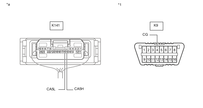
*1 DLC3 - - *a Component with harness connected
(Central Gateway ECU (Network Gateway ECU))
- - Standard Resistance Tester Connection Condition Specified Condition K141-15 (CA5H) - K9-4 (CG) Cable disconnected from negative (-) battery terminal 200 Ω or higher K141-16 (CA5L) - K9-4 (CG) Tech Tips
If the resistance changes to 200 Ω or higher when the connector is disconnected from the ECU or sensor, there may be a short in the ECU or sensor.
Result Result OK NG
OK
REPLACE CORRESPONDING ECU OR SENSOR
NG
REPAIR OR REPLACE CORRESPONDING ECU OR SENSOR CAN BUS LINE OR CONNECTOR
-