CAN COMMUNICATION SYSTEM SYSTEM DESCRIPTION
-
BRIEF DESCRIPTION
-
The Controller Area Network (CAN) is a serial data communication system for real time application. It is a vehicle multiplex communication system which has a high communication speed and the ability to detect malfunctions.
-
Using the CANH and CANL bus lines as a pair, CAN communication is performed using a voltage differential. (A base voltage is applied to the pair of lines and a voltage differential is created when communicating.)
-
Many ECUs or sensors installed on the vehicle operate by sharing information and communicating with each other.
-
The CAN has two resistors of 120 Ω which are necessary to enable communication.
-
-
DEFINITION OF TERMS
-
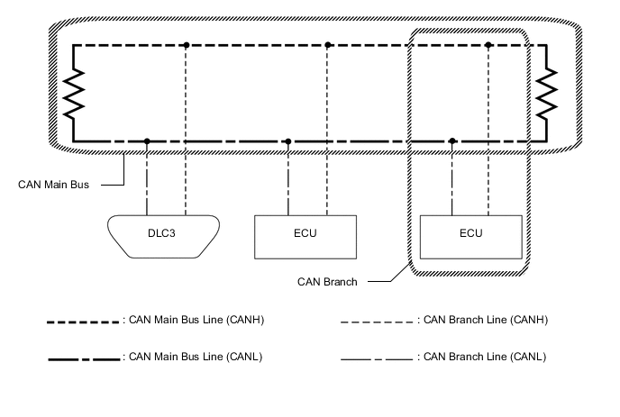
Main bus
-
The main bus is a wire harness between the two terminating resistors on the bus. This is the main bus in the CAN communication system.
-
-
Branch
-
A branch is a wire harness which diverges from the main bus to an ECU or sensor.
-
-
Terminating resistors
-
Two resistors of 120 Ω are installed in parallel across the ends of the CAN main bus lines. They are called terminating resistors. These resistors allow the changes of the voltage differential between the CAN bus lines to be accurately judged. To allow proper function of CAN communication, it is necessary to have both terminating resistors installed. Since the two resistors are installed in parallel, this results in a measurement of approximately 60 Ω.
-
-
-
ECUS OR SENSORS WHICH COMMUNICATE THROUGH CAN COMMUNICATION SYSTEM
-
V Bus
-
Combination meter assembly
-
Power steering ECU assembly
-
Main body ECU (multiplex network body ECU)
-
Steering sensor
-
Airbag sensor assembly
-
ECM
-
Skid control ECU (brake actuator assembly)
-
Air conditioning amplifier assembly
-
Certification ECU (smart key ECU assembly)
-
Yaw rate sensor
-
Headlight leveling ECU assembly
-
Network gateway ECU*1
-
Option connector (bus buffer ECU)*2
-
Telematics transceiver*3
-
Radio receiver assembly
-
Front steering control ECU*4
-
Engine stop and start ECU*5
-
-
Sub Bus 1*17
-
Main body ECU (multiplex network body ECU)
-
Outer mirror control ECU assembly (for driver side)*6
-
Outer mirror control ECU assembly (for front passenger side)*6
-
Front power seat switch LH*6*7
-
Front power seat switch RH*6*8
-
Multiplex tilt and telescopic ECU*9
-
Rear television camera assembly*10
-
-
Sub Bus 2*1
-
Network gateway ECU
-
Driving support ECU assembly*11
-
Absorber control ECU*12
-
Clearance warning ECU assembly*13
-
Lane departure warning camera*14
-
Blind spot monitor sensor LH*15
-
Option connector (bus buffer ECU)*16
-
-
Sub Bus 13*11
-
Driving support ECU assembly
-
Millimeter wave radar sensor assembly
-
-
V3 Bus*4
-
Skid control ECU (brake actuator assembly)
-
Power steering ECU assembly
-
Front steering control ECU
-
Absorber control ECU
-
Tech Tips
*1: w/ Network Gateway ECU
*2: w/o Network Gateway ECU
*3: w/ Telematics Transceiver
*4: w/ VGRS System
*5: w/ Stop and Start System
*6: w/ Seat Position Memory System
*7: for LHD
*8: for RHD
*9: w/ Power Tilt and Power Telescopic System
*10: w/ Parking Assist Monitor System without Parallel Parking Assist Function
*11: w/ Pre-crash Safety System
*12: w/ AVS System
*13: w/ LEXUS Parking Assist-sensor System
*14: w/ Lane Departure Alert System
*15: w/ Blind Spot Monitor System
*16: w/ Option Connector
*17: w/ Seat Position Memory System or Power Tilt and Power Telescopic System
-
-
CIRCUIT DESCRIPTION
-
The V bus, sub bus 1, sub bus 2, V3 bus and sub bus 13 each have termination circuits with two resistors of 120 Ω.
-
-
TROUBLESHOOTING REMARKS
-
DTCs for the CAN communication system can be checked using the GTS. The DLC3 is connected to the CAN communication system, but no DTCs exist regarding problems in the DLC3 or the DLC3 branch lines. If there is a malfunction in the DLC3 or the DLC3 branch lines, ECUs on the CAN cannot output DTCs to the GTS.
-
Malfunctions in the CAN V bus (communication lines) can be checked by measuring the resistance between terminals of the DLC3. However, an open circuit in a branch line other than the DLC3 branch lines cannot be checked from the DLC3 (except for the DLC3 branch lines).
Note
Do not insert the tester probes directly into the DLC3. Be sure to use service wires.
-
-
DIAGNOSTIC TROUBLE CODES FOR CAN COMMUNICATION SYSTEM
-
HOW TO DISTINGUISH CONNECTOR OF CAN JUNCTION CONNECTOR
-
In the CAN communication system, the shape of connectors connected to the CAN junction connector which has an earth terminal are the same. The connectors connected to the CAN junction connector can be distinguished by the colors of the bus lines and the connecting side of the junction connector.
-