CAN COMMUNICATION SYSTEM SYSTEM DIAGRAM
-
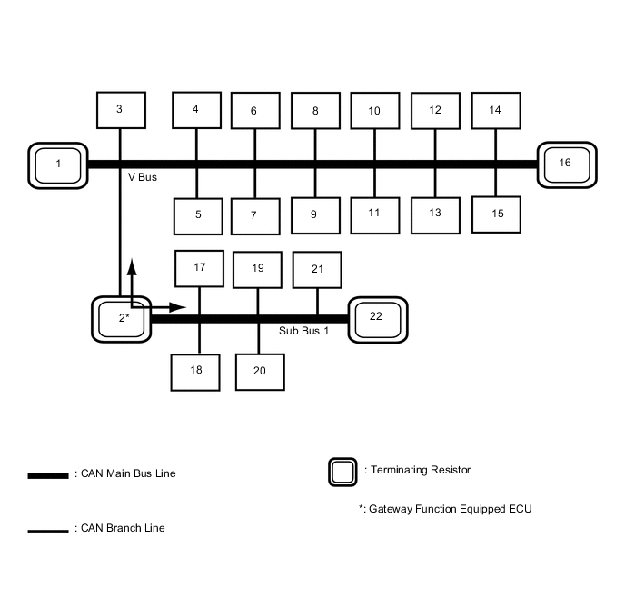
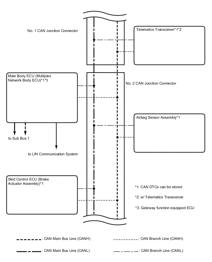
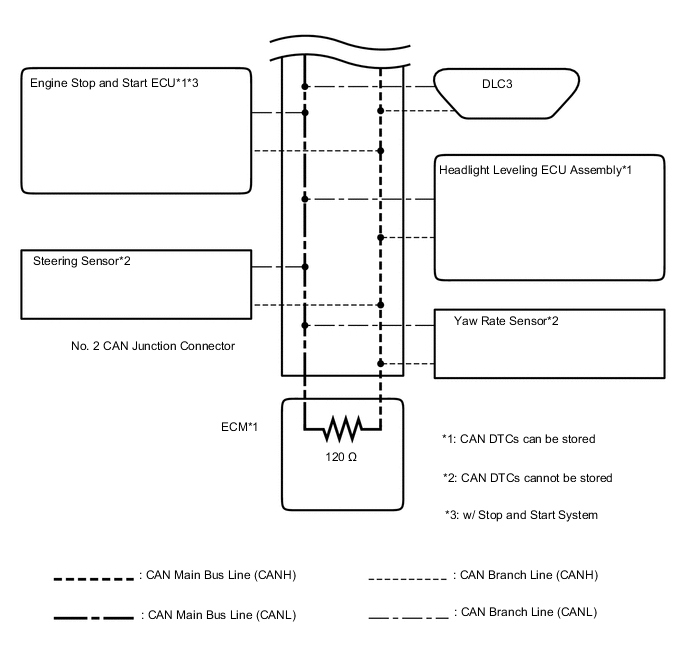
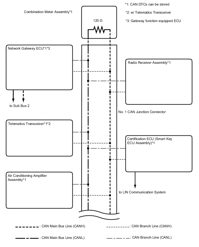
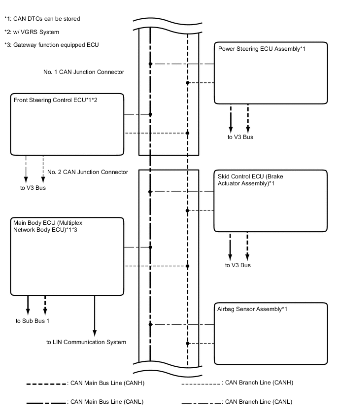
OVERALL CAN BUS DIAGRAM (for LHD)
-
w/o Network Gateway ECU
The CAN communication system is composed of 2 buses.
1 ECM
(for V Bus)
2 Main Body ECU (Multiplex Network Body ECU)
(for V Bus and Sub Bus 1*1)
3 Air Conditioning Amplifier Assembly
(for V Bus)
4 Telematics Transceiver
(w/ Telematics Transceiver)
(for V Bus)
5 Headlight Leveling ECU Assembly
(for V Bus)
6 Certification ECU (Smart Key ECU Assembly)
(for V Bus)
7 Power Steering ECU Assembly
(for V Bus)
8 Steering Sensor
(for V Bus)
9 Skid Control ECU (Brake Actuator Assembly)
(for V Bus)
10 Option Connector (Bus Buffer ECU)
(for V Bus)
11 Airbag Sensor Assembly
(for V Bus)
12 Yaw Rate Sensor
(for V Bus)
13 DLC3
(for V Bus)
14 Radio Receiver Assembly
(for V Bus)
15 Engine Stop and Start ECU
(w/ Stop and Start System)
(for V Bus)
16 Combination Meter Assembly
(for V Bus)
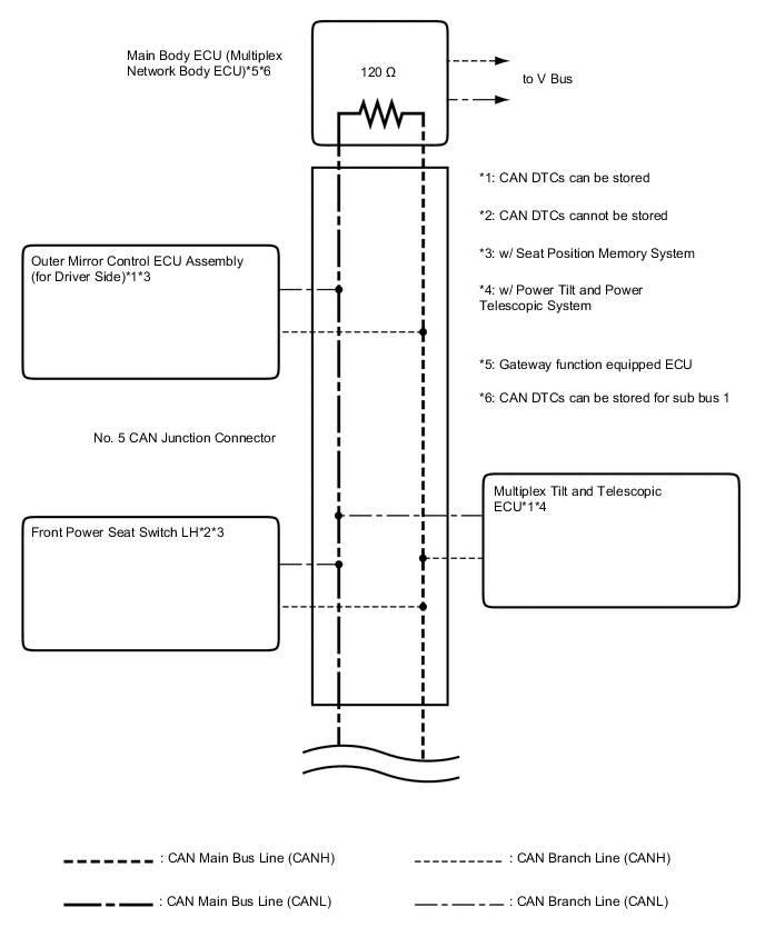
17 Front Power Seat Switch LH
(w/ Seat Position Memory System)
(for Sub Bus 1)
18 Outer Mirror Control ECU Assembly (for Driver Side)
(w/ Seat Position Memory System)
(for Sub Bus 1)
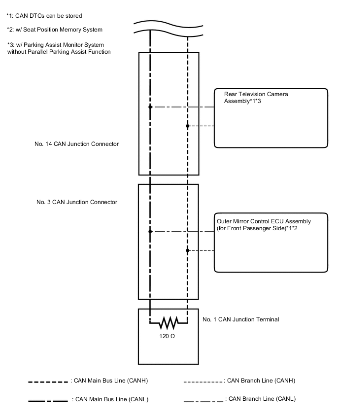
19 Outer Mirror Control ECU Assembly (for Front Passenger Side)
(w/ Seat Position Memory System)
(for Sub Bus 1)
20 Multiplex Tilt and Telescopic ECU
(w/ Power Tilt and Power Telescopic System)
(for Sub Bus 1)
21 Rear Television Camera Assembly
(w/ Parking Assist Monitor System without Parallel Parking Assist Function)
(for Sub Bus 1)
22 No. 1 CAN Junction Terminal
(for Sub Bus 1)
-
*: Seat Position Memory System or Power Tilt and Power Telescopic System
Tech Tips
-
The main body ECU (multiplex network body ECU) functions as a gateway between the V bus and sub bus 1.
-
Refer to the following bus wiring diagrams for details.
-
-
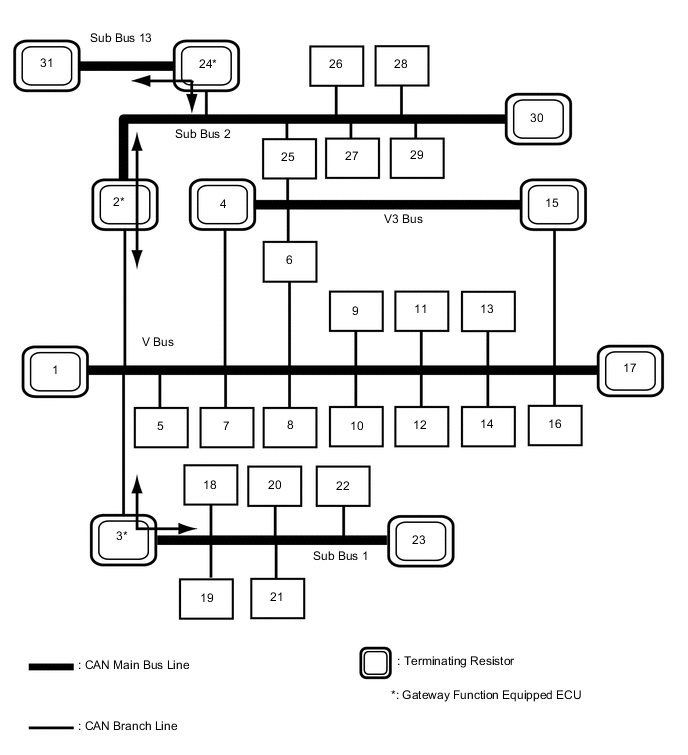
w/ Network Gateway ECU
The CAN communication system is composed of 5 buses.
1 ECM
(for V Bus)
2 Network Gateway ECU
(for V Bus and Sub Bus 2)
3 Main Body ECU (Multiplex Network Body ECU)
(for V Bus and Sub Bus 1*1)
4 Skid Control ECU (Brake Actuator Assembly)
(for V Bus and V3 Bus*2)
5 Telematics Transceiver
(w/ Telematics Transceiver)
(for V Bus)
6 Front Steering Control ECU
(w/ VGRS System)
(for V Bus and V3 Bus)
7 Air Conditioning Amplifier Assembly
(for V Bus)
8 Steering Sensor
(for V Bus)
9 Headlight Leveling ECU Assembly
(for V Bus)
10 Certification ECU (Smart Key ECU Assembly)
(for V Bus)
11 DLC3
(for V Bus)
12 Airbag Sensor Assembly
(for V Bus)
13 Yaw Rate Sensor
(for V Bus)
14 Engine Stop and Start ECU
(w/ Stop and Start System)
(for V Bus)
15 Power Steering ECU Assembly
(for V Bus and V3 Bus*2)
16 Radio Receiver Assembly
(for V Bus)
17 Combination Meter Assembly
(for V Bus)
18 Front Power Seat Switch LH
(w/ Seat Position Memory System)
(for Sub Bus 1)
19 Outer Mirror Control ECU Assembly (for Driver Side)
(w/ Seat Position Memory System)
(for Sub Bus 1)
20 Outer Mirror Control ECU Assembly (for Front Passenger Side)
(w/ Seat Position Memory System)
(for Sub Bus 1)
21 Multiplex Tilt and Telescopic ECU
(w/ Power Tilt and Power Telescopic System)
(for Sub Bus 1)
22 Rear Television Camera Assembly
(w/ Parking Assist Monitor System without Parallel Parking Assist Function)
(for Sub Bus 1)
23 No. 1 CAN Junction Terminal
(for Sub Bus 1)
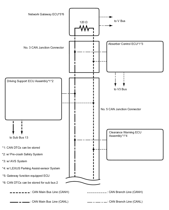
24 Driving Support ECU Assembly
(w/ Pre-crash Safety System)
(for Sub Bus 2 and Sub Bus 13)
25 Absorber Control ECU
(w/ AVS System)
(for Sub Bus 2 and V3 Bus*2)
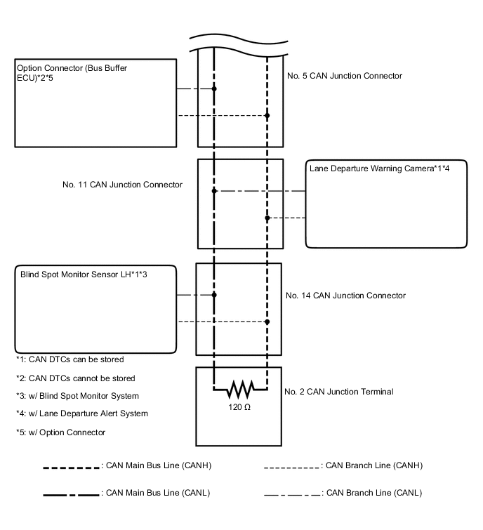
26 Option Connector (Bus Buffer ECU)
(w/ Option Connector)
(for Sub Bus 2)
27 Lane Departure Warning Camera
(w/ Lane Departure Alert System)
(for Sub Bus 2)
28 Clearance Warning ECU Assembly
(w/ LEXUS Parking Assist-sensor System)
(for Sub Bus 2)
29 Blind Spot Monitor Sensor LH
(w/ Blind Spot Monitor System)
(for Sub Bus 2)
30 No. 2 CAN Junction Terminal
(for Sub Bus 2)
31 Millimeter Wave Radar Sensor Assembly
(w/ Pre-crash Safety System)
(for Sub Bus 13)
- -
-
*1: Seat Position Memory System or Power Tilt and Power Telescopic System
-
*2: w/ VGRS System
Tech Tips
-
The main body ECU (multiplex network body ECU) functions as a gateway between the V bus and sub bus 1.
-
The network gateway ECU functions as a gateway between the V bus and sub bus 2.
-
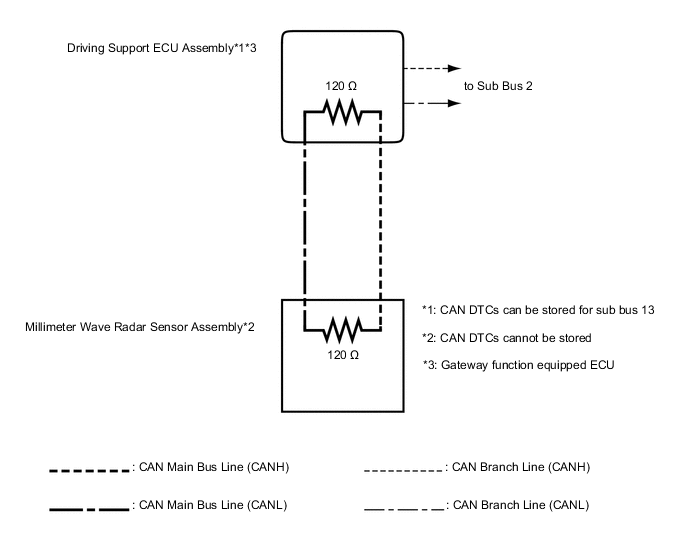
The driving support ECU assembly functions as a gateway between the sub bus 2 and sub bus 13.
-
Refer to the following bus wiring diagrams for details.
-
-
-
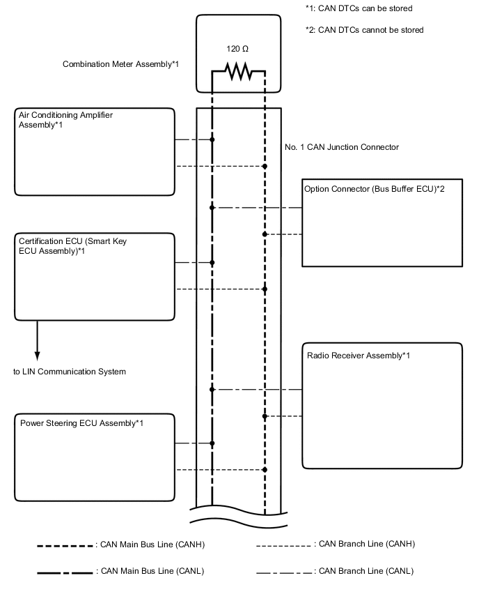
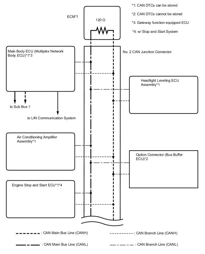
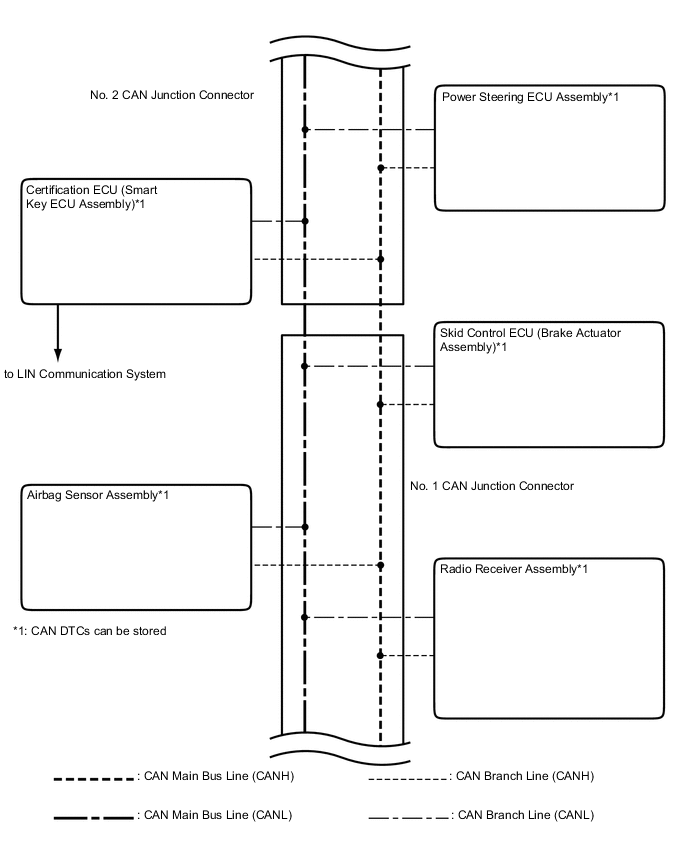
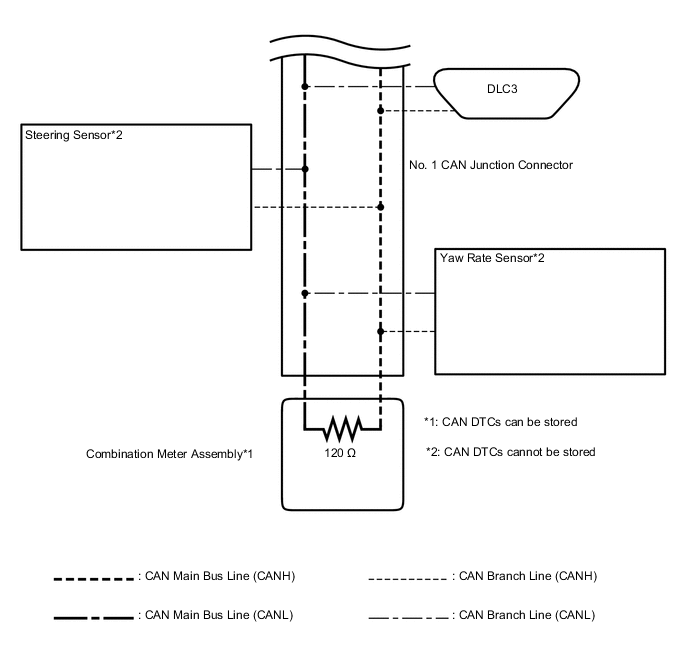
V BUS (for LHD)
-
w/o Network Gateway ECU
Tech Tips
The CAN communication system connects to other networks via ECUs that function as a gateway.
-
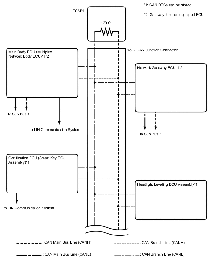
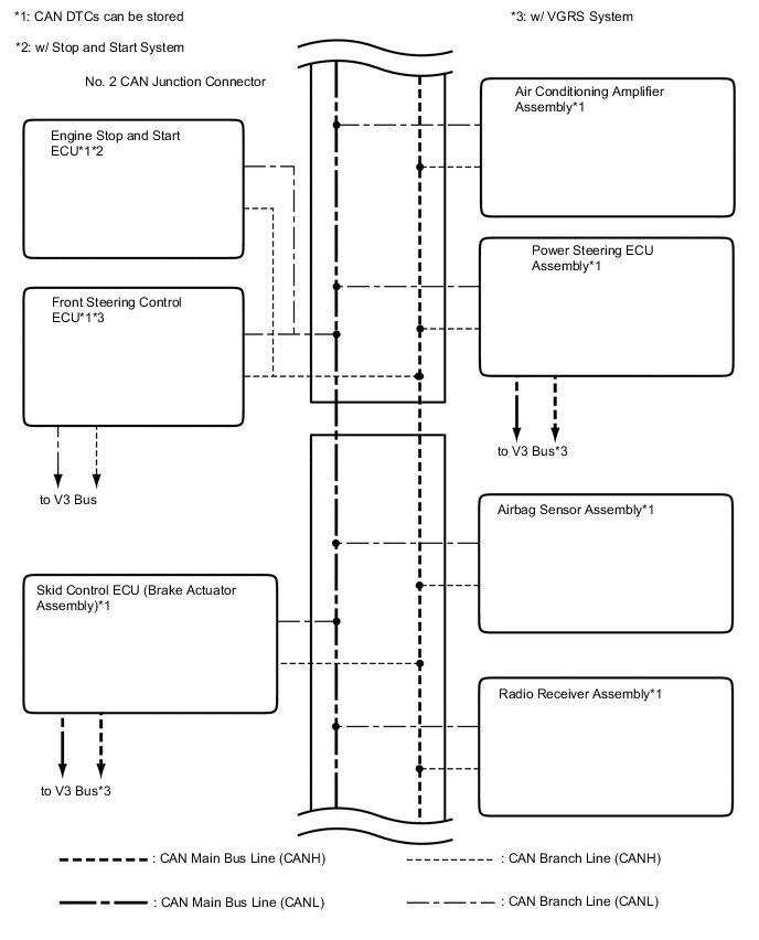
w/ Network Gateway ECU
Tech Tips
The CAN communication system connects to other networks via ECUs that function as a gateway.
-
-
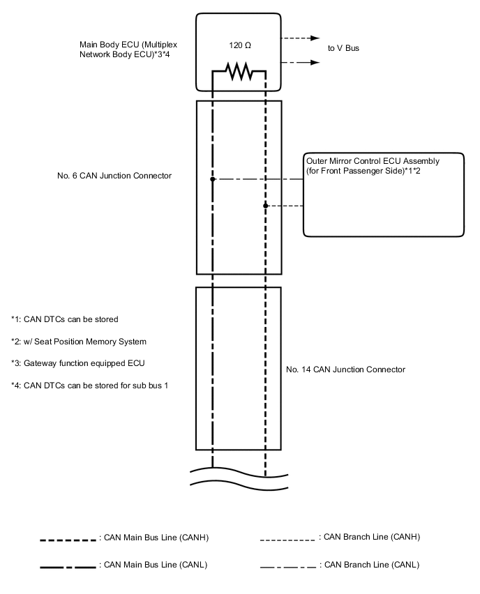
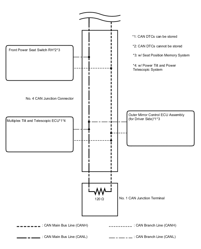
SUB BUS 1 (for LHD with Seat Position Memory System or Power Tilt and Power Telescopic System)
-
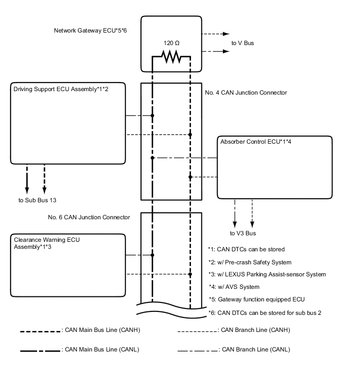
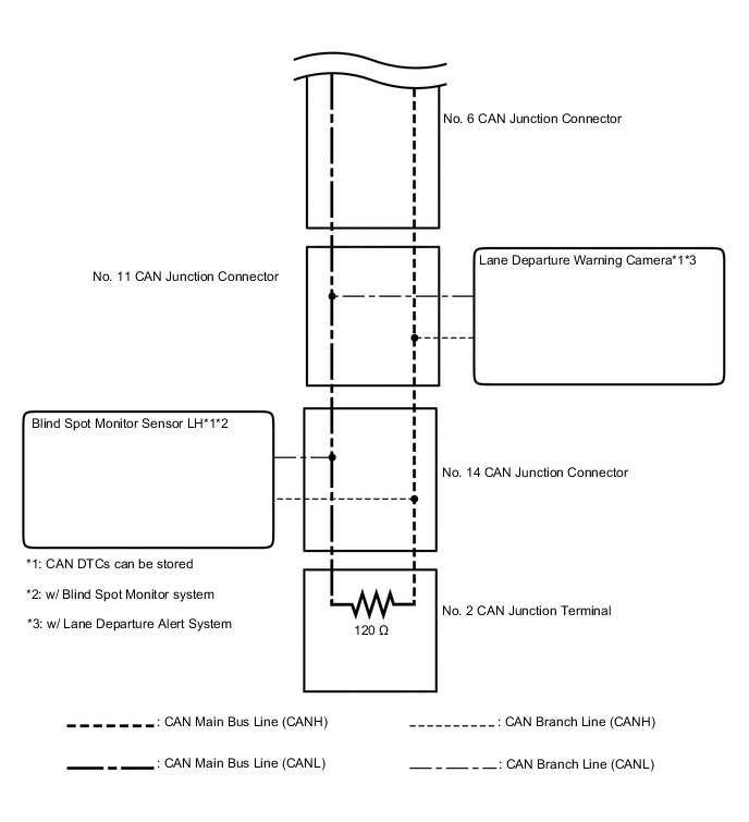
SUB BUS 2 (for LHD with Network Gateway ECU)
-
SUB BUS 13 (for LHD with Pre-crash Safety System)
-
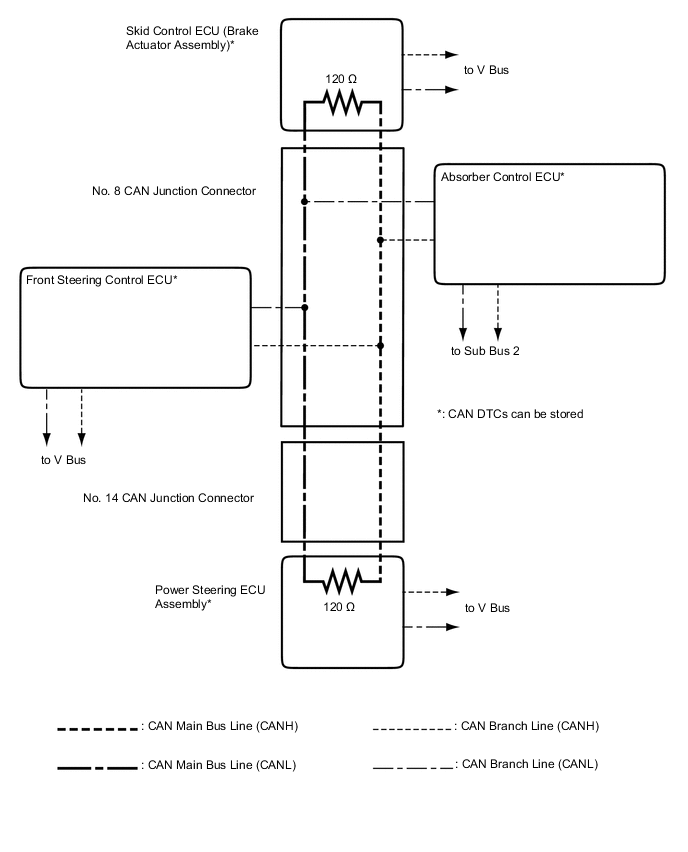
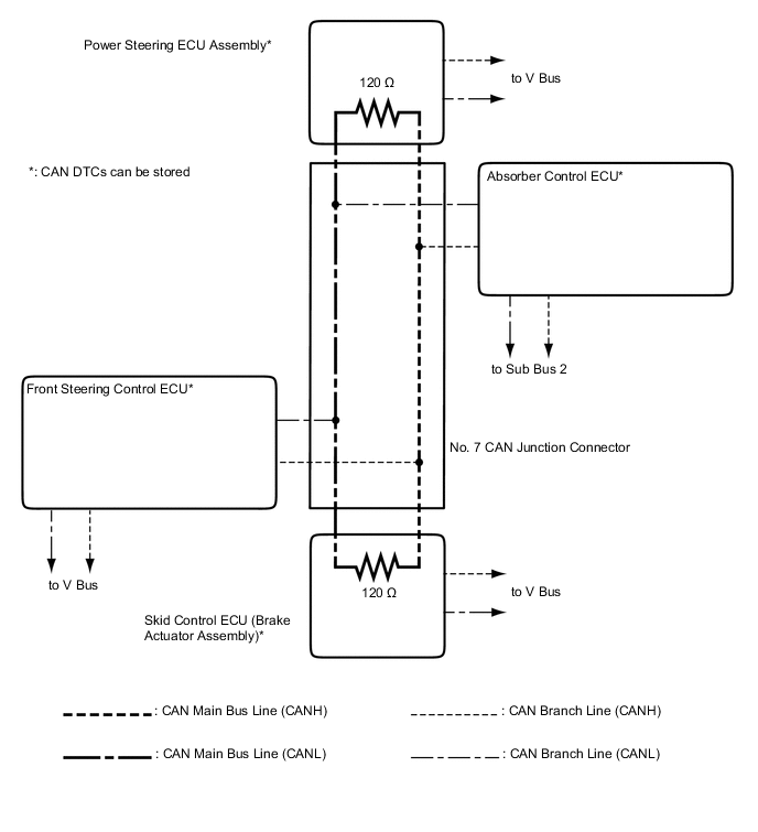
V3 Bus (for LHD with VGRS System)
-
OVERALL CAN BUS DIAGRAM (for RHD)
-
w/o Network Gateway ECU
The CAN communication system is composed of 2 buses.
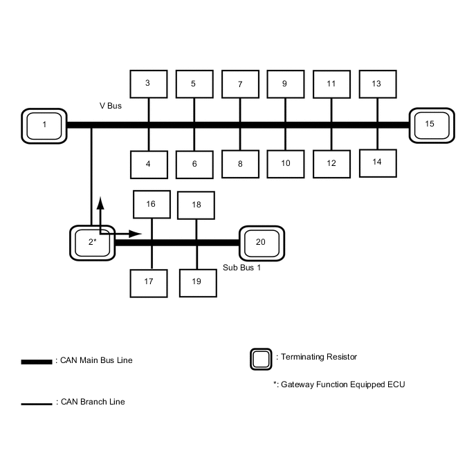
1 ECM
(for V Bus)
2 Main Body ECU (Multiplex Network Body ECU)
(for V Bus and Sub Bus 1*)
3 Air Conditioning Amplifier Assembly
(for V Bus)
4 Headlight Leveling ECU Assembly
(for V Bus)
5 Certification ECU (Smart Key ECU Assembly)
(for V Bus)
6 Power Steering ECU Assembly
(for V Bus)
7 Steering Sensor
(for V Bus)
8 Skid Control ECU (Brake Actuator Assembly)
(for V Bus)
9 Airbag Sensor Assembly
(for V Bus)
10 Yaw Rate Sensor
(for V Bus)
11 Option Connector (Bus Buffer ECU)
(for V Bus)
12 Engine Stop and Start ECU
(w/ Stop and Start System)
(for V Bus)
13 Radio Receiver Assembly
(for V Bus)
14 DLC3
(for V Bus)
15 Combination Meter Assembly
(for V Bus)
16 Outer Mirror Control ECU Assembly (for Driver Side)
(w/ Seat Position Memory System)
(for Sub Bus 1)
17 Outer Mirror Control ECU Assembly (for Front Passenger Side)
(w/ Seat Position Memory System)
(for Sub Bus 1)
18 Multiplex Tilt and Telescopic ECU
(w/ Power Tilt and Power Telescopic System)
(for Sub Bus 1)
19 Front Power Seat Switch RH
(w/ Seat Position Memory System)
(for Sub Bus 1)
20 No. 1 CAN Junction Terminal
(for Sub Bus 1)
-
*: Seat Position Memory System or Power Tilt and Power Telescopic System
Tech Tips
-
The main body ECU (multiplex network body ECU) functions as a gateway between the V bus and sub bus 1.
-
Refer to the following bus wiring diagrams for details.
-
-
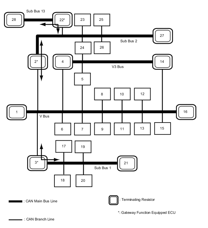
w/ Network Gateway ECU
The CAN communication system is composed of 5 buses.
1 ECM
(for V Bus)
2 Network Gateway ECU
(for V Bus and Sub Bus 2)
3 Main Body ECU (Multiplex Network Body ECU)
(for V Bus and Sub Bus 1*1)
4 Skid Control ECU (Brake Actuator Assembly)
(for V Bus and V3 Bus*2)
5 Front steering Control ECU
(w/ VGRS System)
(for V Bus and V3 Bus)
6 Air Conditioning Amplifier Assembly
(for V Bus)
7 Steering Sensor
(for V Bus)
8 Headlight Leveling ECU Assembly
(for V Bus)
9 Certification ECU (Smart Key ECU Assembly)
(for V Bus)
10 DLC3
(for V Bus)
11 Airbag Sensor Assembly
(for V Bus)
12 Yaw Rate Sensor
(for V Bus)
13 Engine Stop and Start ECU
(w/ Stop and Start System)
(for V Bus)
14 Power Steering ECU Assembly
(for V Bus and V3 Bus*2)
15 Radio Receiver Assembly
(for V Bus)
16 Combination Meter Assembly
(for V Bus)
17 Front Power Seat Switch RH
(w/ Seat Position Memory System)
(for Sub Bus 1)
18 Outer Mirror Control ECU Assembly (for Driver Side)
(w/ Seat Position Memory System)
(for Sub Bus 1)
19 Outer Mirror Control ECU Assembly (for Front Passenger Side)
(w/ Seat Position Memory System)
(for Sub Bus 1)
20 Multiplex Tilt and Telescopic ECU
(w/ Power Tilt and Power Telescopic System)
(for Sub Bus 1)
21 No. 1 CAN Junction Terminal
(for Sub Bus 1)
22 Driving Support ECU Assembly
(w/ Pre-crash Safety System)
(for Sub Bus 2 and Sub Bus 13)
23 Lane Departure Warning Camera
(w/ Lane Departure Alert System)
(for Sub Bus 2)
24 Absorber Control ECU
(w/ AVS System)
(for Sub Bus 2 and V3 Bus*2)
25 Blind Spot Monitor Sensor LH
(w/ Blind Spot Monitor System)
(for Sub Bus 2)
26 Clearance Warning ECU Assembly
(w/ LEXUS Parking Assist-sensor System)
(for Sub Bus 2)
27 No. 2 CAN Junction Terminal
(for Sub Bus 2)
28 Millimeter Wave Radar Sensor Assembly
(w/ Pre-crash Safety System)
(for Sub Bus 13)
-
*1: Seat Position Memory System or Power Tilt and Power Telescopic System
-
*2: w/ VGRS System
Tech Tips
-
The main body ECU (multiplex network body ECU) functions as a gateway between the V bus and sub bus 1.
-
The network gateway ECU functions as a gateway between the V bus and sub bus 2.
-
The driving support ECU assembly functions as a gateway between the sub bus 2 and sub bus 13.
-
Refer to the following bus wiring diagrams for details.
-
-
-
V BUS (for RHD)
-
w/o Network Gateway ECU

Tech Tips
The CAN communication system connects to other networks via ECUs that function as a gateway.
-
w/ Network Gateway ECU
Tech Tips
The CAN communication system connects to other networks via ECUs that function as a gateway.
-
-
SUB BUS 1 (for RHD with Seat Position Memory System or Power Tilt and Power Telescopic System)
-
SUB BUS 2 (for RHD with Network Gateway ECU)
-
SUB BUS 13 (for RHD with Pre-crash Safety System)

-
V3 Bus (for RHD with VGRS System)