CAN COMMUNICATION SYSTEM TERMINALS OF ECU
Note
-
After turning the engine switch off, waiting time may be required before disconnecting the cable from the negative (-) battery terminal. Therefore, make sure to read the disconnecting the cable from the negative (-) battery terminal notices before proceeding with work.
-
Turn the engine switch off before measuring the resistances between CAN main bus lines and between CAN branch lines.
-
Turn the engine switch off before inspecting CAN bus lines for a ground short.
-
Before measuring the resistance of the CAN bus, turn the engine switch off and leave the vehicle for 1 minute or more without operating the key or any switches, or opening or closing the doors. After that, disconnect the cable from the negative (-) battery terminal and leave the vehicle for 1 minute or more before measuring the resistance.
-
This section describes the standard values for all CAN related components.
Tech Tips
-
Operating the engine switch, any other switches or a door triggers related ECU and sensor communication on the CAN. This communication will cause the resistance value to change.
-
Even after DTCs are cleared, if a DTC is stored again after driving the vehicle for a while, the malfunction may be occurring due to vibration of the vehicle. In such a case, wiggling the ECUs or wire harness while performing the inspection below may help determine the cause of the malfunction.
-
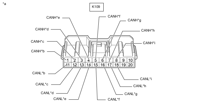
NO. 1 CAN JUNCTION CONNECTOR (for LHD)
-
Check the No. 1 CAN junction connector.
-
Connection diagram
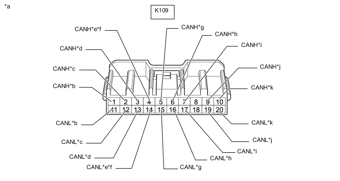
*a Front view of wire harness connector
(to No. 1 CAN Junction Connector)
*b to No. 2 CAN Junction Connector
(for V Bus)
*c to Combination Meter Assembly
(for V Bus)
*d to Radio Receiver Assembly
(for V Bus)
*e to Network Gateway ECU
(w/ Network Gateway ECU)
(for V Bus)
*f to Option Connector (Bus Buffer ECU)
(w/o Network Gateway ECU)
(for V Bus)
*g to Air Conditioning Amplifier Assembly
(for V Bus)
*h to Telematics Transceiver
(w/ Telematics Transceiver)
(for V Bus)
*i to Certification ECU (Smart Key ECU Assembly)
(for V Bus)
*j to Power Steering ECU Assembly
(for V Bus)
*k to Front Steering Control ECU
(w/ VGRS System)
(for V Bus)
- - -
Check the connection diagram of the components which are connected to the No. 1 CAN junction connector.
Terminal No. (Symbol) Wiring Color Connected to K109-1 (CANH) L No. 2 CAN junction connector
(for V bus)
K109-11 (CANL) B K109-2 (CANH) LG Combination meter assembly
(for V bus)
K109-12 (CANL) B K109-3 (CANH) R Radio receiver assembly
(for V bus)
K109-13 (CANL) B K109-4 (CANH) BE Network gateway ECU*1
(for V bus)
K109-14 (CANL) B K109-4 (CANH) BE Option connector (bus buffer ECU)*2
(for V bus)
K109-14 (CANL) B K109-5 (CANH) P Air conditioning amplifier assembly
(for V bus)
K109-15 (CANL) B K109-6 (CANH) V Telematics transceiver*3
(for V bus)
K109-16 (CANL) B K109-7 (CANH) W Certification ECU (smart key ECU assembly)
(for V bus)
K109-17 (CANL) B K109-9 (CANH) G Power steering ECU assembly
(for V Bus)
K109-19 (CANL) B K109-10 (CANH) GR Front steering control ECU*4
(for V bus)
K109-20 (CANL) B
-
*1: w/ Network Gateway ECU
-
*2: w/o Network Gateway ECU
-
*3: w/ Telematics Transceiver
-
*4: w/ VGRS System
-
-
-
-
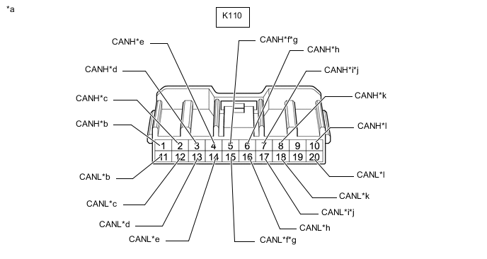
NO. 2 CAN JUNCTION CONNECTOR (for LHD)
-
Check the No. 2 CAN junction connector.
-
Connection diagram
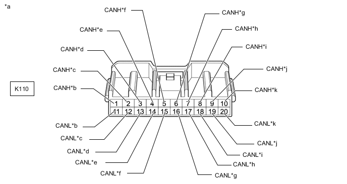
*a Front view of wire harness connector
(to No. 2 CAN Junction Connector)
*b to No. 1 CAN Junction Connector
(for V Bus)
*c to Main Body ECU (Multiplex Network Body ECU)
(for V Bus)
*d to ECM
(for V Bus)
*e to Headlight Leveling ECU Assembly
(for V Bus)
*f to Airbag Sensor Assembly
(for V Bus)
*g to Yaw Rate Sensor
(for V Bus)
*h to Engine Stop and Start ECU
(for V Bus)
*i to DLC3
(for V Bus)
*j to Steering Sensor
(for V Bus)
*k to Skid Control ECU (Brake Actuator Assembly)
(for V Bus)
- - -
Check the connection diagram of the components which are connected to the No. 2 CAN junction connector.
Terminal No. (Symbol) Wiring Color Connected to K110-1 (CANH) L No. 1 CAN junction connector
(for V bus)
K110-11 (CANL) B K110-2 (CANH) Y Main body ECU (multiplex network body ECU)
(for V bus)
K110-12 (CANL) B K110-3 (CANH) R ECM
(for V bus)
K110-13 (CANL) B K110-4 (CANH) LG Headlight leveling ECU assembly
(for V bus)
K110-14 (CANL) B K110-5 (CANH) BE Airbag sensor assembly
(for V bus)
K110-15 (CANL) B K110-6 (CANH) G Yaw rate sensor
(for V bus)
K110-16 (CANL) B K110-7 (CANH) GR Engine stop and start ECU*
(for V bus)
K110-17 (CANL) B K110-8 (CANH) W DLC3
(for V bus)
K110-18 (CANL) B K110-9 (CANH) P Steering sensor
(for V bus)
K110-19 (CANL) B K110-10 (CANH) SB Skid control ECU (brake actuator assembly)
(for V bus)
K110-20 (CANL) B
-
*: w/ Stop and Start System
-
-
-
-
NO. 3 CAN JUNCTION CONNECTOR (for LHD)
-
Check the No. 3 CAN junction connector.
-
Connection diagram
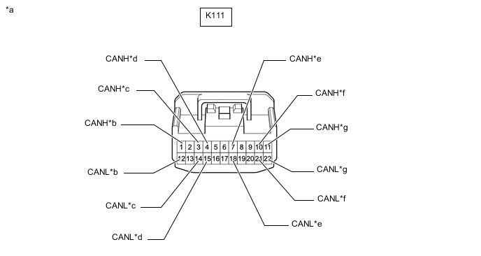
*a Front view of wire harness connector
(to No. 3 CAN Junction Connector)
*b to Absorber Control ECU
(w/ AVS System)
(for Sub Bus 2)
*c to No. 5 CAN Junction Connector
(for Sub Bus 2)
*d to Network Gateway ECU
(for Sub Bus 2)
*e to No. 14 CAN Junction Connector
(for Sub Bus 1)
*f to Outer Mirror Control ECU Assembly (for Front Passenger Side)
(w/ Seat Position Memory System)
(for Sub Bus 1)
*g to No. 1 CAN Junction Terminal
(for Sub Bus 1)
- - -
Check the connection diagram of the components which are connected to the No. 3 CAN junction connector.
Terminal No. (Symbol) Wiring Color Connected to K111-1 (CANH) SB Absorber control ECU*1
(for Sub bus 2)
K111-12 (CANL) B K111-3 (CANH) L No. 5 CAN junction connector
(for Sub bus 2)
K111-14 (CANL) B K111-4 (CANH) R Network gateway ECU
(for Sub bus 2)
K111-15 (CANL) B K111-7 (CANH) LG No. 14 CAN junction connector
(for Sub bus 1)
K111-18 (CANL) B K111-10 (CANH) W Outer mirror control ECU assembly (for front passenger side)*2
(for Sub bus 1)
K111-21 (CANL) B K111-11 (CANH) P No. 1 CAN junction terminal
(for Sub bus 1)
K111-22 (CANL) B
-
*1: w/ AVS System
-
*2: w/ Seat Position Memory System
-
-
-
-
NO. 5 CAN JUNCTION CONNECTOR (for LHD)
-
Check the No. 5 CAN junction connector.
-
Connection diagram
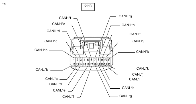
*a Front view of wire harness connector
(to No. 5 CAN Junction Connector)
*b to No. 3 CAN Junction Connector
(for Sub Bus 2)
*c to No. 11 CAN Junction Connector
(for Sub Bus 2)
*d to Option Connector (Bus Buffer ECU)
(w/ Option Connector)
(for Sub Bus 2)
*e to Driving Support ECU Assembly
(w/ Pre-crash Safety System)
(for Sub Bus 2)
*f to Clearance Warning ECU Assembly
(w/ LEXUS Parking Assist-sensor System)
(for Sub Bus 2)
*g to No. 14 CAN Junction Connector
(for Sub Bus 1)
*h to Main Body ECU (Multiplex Network Body ECU)
(for Sub Bus 1)
*i to Outer Mirror Control ECU Assembly (for Driver side)
(w/ Seat Position Memory System)
(for Sub Bus 1)
*j to Multiplex Tilt and Telescopic ECU
(w/ Power Tilt and Power Telescopic System)
(for Sub Bus 1)
*k to Front Power Seat Switch LH
(w/ Seat Position Memory System)
(for Sub Bus 1)
- - -
Check the connection diagram of the components which are connected to the No. 5 CAN junction connector.
Terminal No. (Symbol) Wiring Color Connected to K113-1 (CANH) L No. 3 CAN junction connector
(for Sub bus 2)
K113-12 (CANL) B K113-2 (CANH) LG No. 11 CAN junction connector
(for Sub bus 2)
K113-13 (CANL) B K113-3 (CANH) R Option connector (bus buffer ECU)*1
(for Sub bus 2)
K113-14 (CANL) B K113-5 (CANH) G Driving support ECU assembly*2
(for Sub bus 2)
K113-16 (CANL) B K113-6 (CANH) SB Clearance warning ECU assembly*3
(for Sub bus 2)
K113-17 (CANL) B K113-7 (CANH) L No. 14 CAN junction connector
(for Sub bus 1)
K113-18 (CANL) B K113-8 (CANH) P Main body ECU (multiplex network body ECU)
(for Sub bus 1)
K113-19 (CANL) B K113-9 (CANH) W Outer mirror control ECU assembly (for driver side)*4
(for Sub bus 1)
K113-20 (CANL) B K113-10 (CANH) G Multiplex tilt and telescopic ECU*5
(for Sub bus 1)
K113-21 (CANL) B K113-11 (CANH) R Front power seat switch LH*4
(for Sub bus 1)
K113-22 (CANL) B
-
*1: w/ Option Connector
-
*2: w/ Pre-crash Safety System
-
*3: w/ LEXUS Parking Assist-sensor System
-
*4: w/ Seat Position Memory System
-
*5: w/ Power Tilt and Power Telescopic System
-
-
-
-
NO. 7 CAN JUNCTION CONNECTOR (for LHD)
-
Check the No. 7 CAN junction connector.
-
Connection diagram

*a Front view of wire harness connector
(to No. 7 CAN Junction Connector)
*b to Front Steering Control ECU
(for V3 Bus)
*c to Power Steering ECU Assembly
(for V3 Bus)
*d to Skid Control ECU (Brake Actuator Assembly)
(for V3 Bus)
*e to Absorber Control ECU
(for V3 Bus)
- - -
Check the connection diagram of the components which are connected to the No. 7 CAN junction connector.
Terminal No. (Symbol) Wiring Color Connected to K115-1 (CANH) R Front steering control ECU
(for V3 bus)
K115-12 (CANL) B K115-2 (CANH) W Power steering ECU assembly
(for V3 bus)
K115-13 (CANL) B K115-3 (CANH) LG Skid control ECU (brake actuator assembly)
(for V3 bus)
K115-14 (CANL) B K115-5 (CANH) G Absorber control ECU
(for V3 bus)
K115-16 (CANL) B
-
-
-
NO. 11 CAN JUNCTION CONNECTOR (for LHD)
-
Check the No. 11 CAN junction connector.
-
Connection diagram
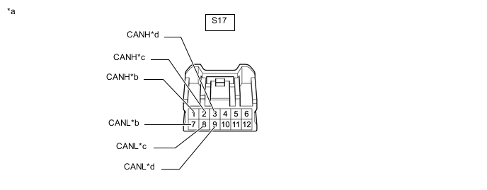
*a Front view of wire harness connector
(to No. 11 CAN Junction Connector)
*b to No. 5 CAN Junction Connector
(for Sub Bus 2)
*c to No. 14 CAN Junction Connector
(for Sub Bus 2)
*d to Lane Departure Warning Camera
(w/ Lane Departure Alert System)
(for Sub Bus 2)
-
Check the connection diagram of the components which are connected to the No. 11 CAN junction connector.
Terminal No. (Symbol) Wiring Color Connected to S17-1 (CANH) LG No. 5 CAN junction connector
(for Sub bus 2)
S17-7 (CANL) B S17-2 (CANH) BE No. 14 CAN junction connector
(for Sub bus 2)
S17-8 (CANL) B S17-3 (CANH) R Lane departure warning camera*
(for Sub bus 2)
S17-9 (CANL) B
-
*: w/ Lane Departure Alert System
-
-
-
-
NO. 14 CAN JUNCTION CONNECTOR (for LHD)
-
Check the No. 14 CAN junction connector.
-
Connection diagram
*a Front view of wire harness connector
(to No. 14 CAN Junction Connector)
*b to No. 11 CAN Junction Connector
(for Sub Bus 2)
*c to No. 2 CAN Junction Terminal
(for Sub Bus 2)
*d to Blind Spot Monitor Sensor LH
(w/ Blind Spot Monitor System)
(for Sub Bus 2)
*e to No. 3 CAN Junction Connector
(for Sub Bus 1)
*f to No. 5 CAN Junction Connector
(for Sub Bus 1)
*g to Rear Television Camera Assembly
(w/ Parking Assist Monitor System without Parallel Parking Assist Function)
(for Sub Bus 1)
- - -
Check the connection diagram of the components which are connected to the No. 14 CAN junction connector.
Terminal No. (Symbol) Wiring Color Connected to Q57-1 (CANH) BE No. 11 CAN junction connector
(for Sub bus 2)
Q57-12 (CANL) B Q57-2 (CANH) V No. 2 CAN junction terminal
(for Sub bus 2)
Q57-13 (CANL) B Q57-3 (CANH) R Blind spot monitor sensor LH*1
(for Sub bus 2)
Q57-14 (CANL) B Q57-9 (CANH) LG No. 3 CAN junction connector
(for Sub bus 1)
Q57-20 (CANL) B Q57-10 (CANH) L No. 5 CAN junction connector
(for Sub bus 1)
Q57-21 (CANL) B Q57-11 (CANH) W Rear television camera assembly*2 Q57-22 (CANL) B
-
*1: w/ Blind Spot Monitor System
-
*2: w/ Parking Assist Monitor System without Parallel Parking Assist Function
-
-
-
-
NO. 1 CAN JUNCTION CONNECTOR (for RHD)
-
Check the No. 1 CAN junction connector.
-
Connection diagram
*a Front view of wire harness connector
(to No. 1 CAN Junction Connector)
*b to No. 2 CAN Junction Connector
(for V Bus)
*c to Combination Meter Assembly
(for V Bus)
*d to Radio Receiver Assembly
(for V Bus)
*e to Airbag Sensor Assembly
(for V Bus)
*f to Yaw Rate Sensor
(for V Bus)
*g to Skid Control ECU (Brake Actuator Assembly)
(for V Bus)
*h to Steering Sensor
(for V Bus)
*i to DLC3
(for V Bus)
- - -
Check the connection diagram of the components which are connected to the No. 1 CAN junction connector.
Terminal No. (Symbol) Wiring Color Connected to K109-1 (CANH) L No. 2 CAN junction connector
(for V bus)
K109-11 (CANL) B K109-2 (CANH) LG Combination meter assembly
(for V bus)
K109-12 (CANL) B K109-3 (CANH) R Radio receiver assembly
(for V bus)
K109-13 (CANL) B K109-4 (CANH) BE Airbag sensor assembly
(for V bus)
K109-14 (CANL) B K109-5 (CANH) G Yaw rate sensor
(for V bus)
K109-15 (CANL) B K109-6 (CANH) SB Skid control ECU (brake actuator assembly)
(for V bus)
K109-16 (CANL) B K109-7 (CANH) P Steering sensor
(for V bus)
K109-17 (CANL) B K109-8 (CANH) W DLC3
(for V bus)
K109-18 (CANL) B
-
-
-
NO. 2 CAN JUNCTION CONNECTOR (for RHD)
-
Check the No. 2 CAN junction connector.
-
Connection diagram
*a Front view of wire harness connector
(to No. 2 CAN Junction Connector)
*b to No. 1 CAN Junction Connector
(for V Bus)
*c to Main Body ECU (Multiplex Network Body ECU)
(for V Bus)
*d to ECM
(for V Bus)
*e to Headlight Leveling ECU Assembly
(for V Bus)
*f to Network Gateway ECU
(w/ Network Gateway ECU)
(for V Bus)
*g to Option Connector (Bus Buffer ECU)
(w/o Network Gateway ECU)
(for V Bus)
*h to Air Conditioning Amplifier Assembly
(for V Bus)
*i to Front Steering Control ECU
(w/ VGRS System)
(for V Bus)
*j to Engine Stop and Start ECU
(w/ Stop and Start System)
(for V Bus)
*k to Certification ECU (Smart Key ECU Assembly)
(for V Bus)
*l to Power Steering ECU Assembly
(for V Bus)
-
Check the connection diagram of the components which are connected to the No. 2 CAN junction connector.
Terminal No. (Symbol) Wiring Color Connected to K110-1 (CANH) L No. 1 CAN junction connector
(for V bus)
K110-11 (CANL) B K110-2 (CANH) Y Main body ECU (multiplex network body ECU)
(for V bus)
K110-12 (CANL) B K110-3 (CANH) R ECM
(for V bus)
K110-13 (CANL) B K110-4 (CANH) LG Headlight leveling ECU assembly
(for V bus)
K110-14 (CANL) B K110-5 (CANH) BE Network gateway ECU*1
(for V bus)
K110-15 (CANL) B K110-5 (CANH) BE Option connector (bus buffer ECU)*2
(for V bus)
K110-15 (CANL) B K110-6 (CANH) P Air conditioning amplifier assembly
(for V bus)
K110-16 (CANL) B K110-7 (CANH) GR Front steering control ECU*3
(for V bus)
K110-17 (CANL) B K110-7 (CANH) GR Engine stop and start ECU*4
(for V bus)
K110-17 (CANL) B K110-8 (CANH) W Certification ECU (smart key ECU assembly)
(for V bus)
K110-18 (CANL) B K110-10 (CANH) G Power steering ECU assembly
(for V bus)
K110-20 (CANL) B
-
*1: w/ Network Gateway ECU
-
*2: w/o Network Gateway ECU
-
*3: w/ VGRS System
-
*4: w/ Stop and Start System
-
-
-
-
NO. 4 CAN JUNCTION CONNECTOR (for RHD)
-
Check the No. 4 CAN junction connector.
-
Connection diagram
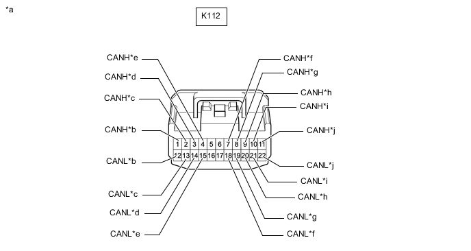
*a Front view of wire harness connector
(to No. 4 CAN Junction Connector)
*b to Absorber Control ECU
(w/ AVS System)
(for Sub Bus 2)
*c to Driving Support ECU Assembly
(w/ Pre-crash Safety System)
(for Sub Bus 2)
*d to No. 6 CAN Junction Connector
(for Sub Bus 2)
*e to Network Gateway ECU
(w/ Network Gateway ECU)
(for Sub Bus 2)
*f to No. 14 CAN Junction Connector
(for Sub Bus 1)
*g to Multiplex Tilt and Telescopic ECU
(w/ Power Tilt and Power Telescopic System)
(for Sub Bus 1)
*h to Front Power Seat Switch RH
(w/ Seat Position Memory System)
(for Sub Bus 1)
*i to Outer Mirror Control ECU Assembly (for Driver side)
(w/ Seat Position Memory System)
(for Sub Bus 1)
*j to No. 1 CAN Junction Terminal
(for Sub Bus 1)
-
Check the connection diagram of the components which are connected to the No. 4 CAN junction connector.
Terminal No. (Symbol) Wiring Color Connected to K112-1 (CANH) SB Absorber control ECU*1
(for Sub bus 2)
K112-12 (CANL) B K112-2 (CANH) G Driving support ECU assembly*2
(for Sub bus 2)
K112-13 (CANL) B K112-3 (CANH) L No. 6 CAN junction connector
(for Sub bus 2)
K112-14 (CANL) B K112-4 (CANH) R Network gateway ECU*3
(for Sub bus 2)
K112-15 (CANL) B K112-7 (CANH) LG No. 14 CAN junction connector
(for Sub bus 1)
K112-18 (CANL) B K112-8 (CANH) G Multiplex tilt and telescopic ECU*4
(for Sub bus 1)
K112-19 (CANL) B K112-9 (CANH) R Front power seat switch RH*5
(for Sub bus 1)
K112-20 (CANL) B K112-10 (CANH) W Outer mirror control ECU assembly (for driver side)*5
(for Sub bus 1)
K112-21 (CANL) B K112-11 (CANH) P No. 1 CAN junction terminal
(for Sub bus 1)
K112-22 (CANL) B
-
*1: w/ AVS System
-
*2: w/ Pre-crash Safety System
-
*3: w/ Network Gateway ECU
-
*4: w/ Power Tilt and Power Telescopic System
-
*5: w/ Seat Position Memory System
-
-
-
-
NO. 6 CAN JUNCTION CONNECTOR (for RHD)
-
Check the No. 6 CAN junction connector.
-
Connection diagram
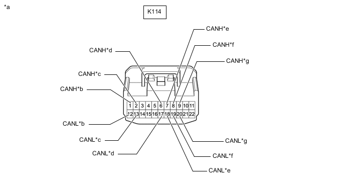
*a Front view of wire harness connector
(to No. 6 CAN Junction Connector)
*b to No. 4 CAN Junction Connector
(for Sub Bus 2)
*c to No. 11 CAN Junction Connector
(for Sub Bus 2)
*d to Clearance Warning ECU Assembly
(w/ LEXUS Parking Assist-sensor System)
(for Sub Bus 2)
*e to No. 14 CAN Junction Connector
(for Sub Bus 1)
*f to Main Body ECU (Multiplex Network Body ECU)
(for Sub Bus 1)
*g to Outer Mirror Control ECU Assembly (for Front Passenger Side)
(w/ Seat Position Memory System)
(for Sub Bus 1)
- - -
Check the connection diagram of the components which are connected to the No. 6 CAN junction connector.
Terminal No. (Symbol) Wiring Color Connected to K114-1 (CANH) L No. 4 CAN junction connector
(for Sub bus 2)
K114-12 (CANL) B K114-2 (CANH) LG No. 11 CAN junction connector
(for Sub bus 2)
K114-13 (CANL) B K114-6 (CANH) SB Clearance warning ECU assembly*1
(for Sub bus 2)
K114-17 (CANL) B K114-7 (CANH) L No. 14 CAN junction connector
(for Sub bus 1)
K114-18 (CANL) B K114-8 (CANH) P Main body ECU (multiplex network body ECU)
(for Sub bus 1)
K114-19 (CANL) B K114-9 (CANH) W Outer mirror control ECU assembly (for front passenger side)*2
(for Sub bus 1)
K114-20 (CANL) B
-
*1: w/ LEXUS Parking Assist-sensor System
-
*2: w/ Seat Position Memory System
-
-
-
-
NO. 8 CAN JUNCTION CONNECTOR (for RHD)
-
Check the No. 8 CAN junction connector.
-
Connection diagram
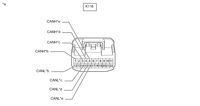
*a Front view of wire harness connector
(to No. 8 CAN Junction Connector)
*b to Front Steering Control ECU
(for V3 Bus)
*c to Skid Control ECU (Brake Actuator Assembly)
(for V3 Bus)
*d to No. 14 CAN Junction Connector
(for V3 Bus)
*e to Absorber Control ECU
(for V3 Bus)
- - -
Check the connection diagram of the components which are connected to the No. 8 CAN junction connector.
Terminal No. (Symbol) Wiring Color Connected to K116-1 (CANH) R Front steering control ECU
(for V3 bus)
K116-12 (CANL) B K116-3 (CANH) LG Skid control ECU (brake actuator assembly)
(for V3 bus)
K116-14 (CANL) B K116-4 (CANH) P No. 14 CAN junction connector
(for V3 bus)
K116-15 (CANL) B K116-5 (CANH) G Absorber control ECU
(for V3 bus)
K116-16 (CANL) B
-
-
-
NO. 11 CAN JUNCTION CONNECTOR (for RHD)
-
Check the No. 11 CAN junction connector.
-
Connection diagram
*a Front view of wire harness connector
(to No. 11 CAN Junction Connector)
*b to No. 6 CAN Junction Connector
(for Sub Bus 2)
*c to No. 14 CAN Junction Connector
(for Sub Bus 2)
*d to Lane Departure Warning Camera
(w/ Lane Departure Alert System)
(for Sub Bus 2)
-
Check the connection diagram of the components which are connected to the No. 11 CAN junction connector.
Terminal No. (Symbol) Wiring Color Connected to S17-1 (CANH) LG No. 6 CAN junction connector
(for Sub bus 2)
S17-7 (CANL) B S17-2 (CANH) BE No. 14 CAN junction connector
(for Sub bus 2)
S17-8 (CANL) B S17-3 (CANH) R Lane departure warning camera*
(for Sub bus 2)
S17-9 (CANL) B
-
*: w/ Lane Departure Alert System
-
-
-
-
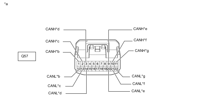
NO. 14 CAN JUNCTION CONNECTOR (for RHD)
-
Check the No. 14 CAN junction connector.
-
Connection diagram
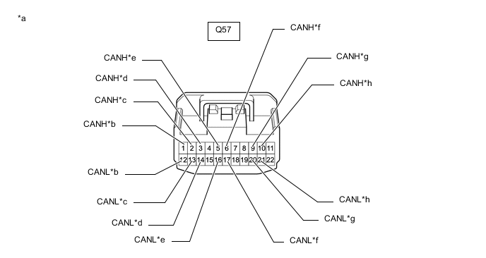
*a Front view of wire harness connector
(to No. 14 CAN Junction Connector)
*b to No. 11 CAN Junction Connector
(for Sub Bus 2)
*c to No. 2 CAN Junction Terminal
(for Sub Bus 2)
*d to Blind Spot Monitor Sensor LH
(w/ Blind Spot Monitor System)
(for Sub Bus 2)
*e to No. 8 CAN Junction Connector
(for V3 Bus)
*f to Power Steering ECU Assembly
(w/ VGRS System)
(for V3 Bus)
*g to No. 4 CAN Junction Connector
(for Sub Bus 1)
*h to No. 6 CAN Junction Connector
(for Sub Bus 1)
-
Check the connection diagram of the components which are connected to the No. 14 CAN junction connector.
Terminal No. (Symbol) Wiring Color Connected to Q57-1 (CANH) BE No. 11 CAN junction connector
(for Sub bus 2)
Q57-12 (CANL) B Q57-2 (CANH) V No. 2 CAN junction terminal
(for Sub bus 2)
Q57-13 (CANL) B Q57-3 (CANH) R Blind spot monitor sensor LH*1
(for Sub bus 2)
Q57-14 (CANL) B Q57-5 (CANH) P No. 8 CAN junction connector
(for V3 bus)
Q57-16 (CANL) B Q57-6 (CANH) W Power steering ECU assembly*2
(for V3 bus)
Q57-17 (CANL) B Q57-9 (CANH) LG No. 4 CAN junction connector
(for Sub bus 1)
Q57-20 (CANL) B Q57-10 (CANH) L No. 6 CAN junction connector
(for Sub bus 1)
Q57-21 (CANL) B
-
*1: w/ Blind Spot Monitor System
-
*2: w/ VGRS System
-
-
-
-
NO. 1 CAN JUNCTION TERMINAL (for LHD)
-
Check the No. 1 CAN junction terminal.
-
Connection diagram

*a Front view of wire harness connector
(to No. 1 CAN Junction Terminal)
*b to No. 3 CAN Junction Connector
(for Sub Bus 1)
-
Check the connection diagram of the components which are connected to the No. 1 CAN junction terminal.
Terminal No. (Symbol) Wiring Color Connected to K106-3 (CANH) P No. 3 CAN junction connector
(for Sub bus 1)
K106-2 (CANL) B
-
-
-
NO. 1 CAN JUNCTION TERMINAL (for RHD)
-
Check the No. 1 CAN junction terminal.
-
Connection diagram
*a Front view of wire harness connector
(to No. 1 CAN Junction Terminal)
*b to No. 4 CAN Junction Connector
(for Sub Bus 1)
-
Check the connection diagram of the components which are connected to the No. 1 CAN junction terminal.
Terminal No. (Symbol) Wiring Color Connected to K106-3 (CANH) P No. 4 CAN junction connector
(for Sub bus 1)
K106-2 (CANL) B
-
-
-
NO. 2 CAN JUNCTION TERMINAL
-
Check the No. 2 CAN junction terminal.
-
Connection diagram

*a Front view of wire harness connector
(to No. 2 CAN Junction Terminal)
*b to No. 14 CAN Junction Connector
(for Sub Bus 2)
-
Check the connection diagram of the components which are connected to the No. 2 CAN junction terminal.
Terminal No. (Symbol) Wiring Color Connected to K107-3 (CANH) V No. 14 CAN junction connector
(for Sub bus 2)
K107-2 (CANL) B
-
-
-
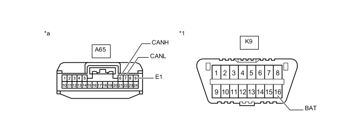
DLC3
-
Disconnect the cable from the negative (-) battery terminal.
-
Measure the resistance according to the value(s) in the table below.
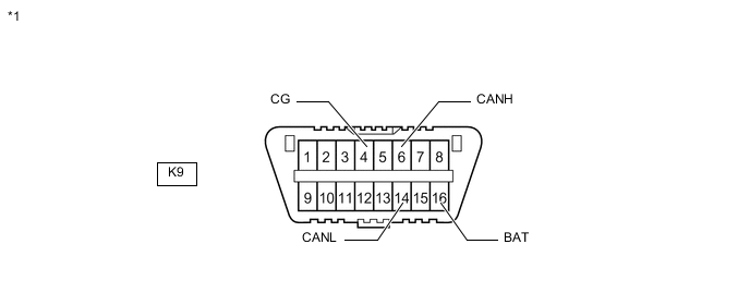
*1 DLC3 - -
-
-
ECM (for 2GR-FSE)
-
Disconnect the cable from the negative (-) battery terminal.
-
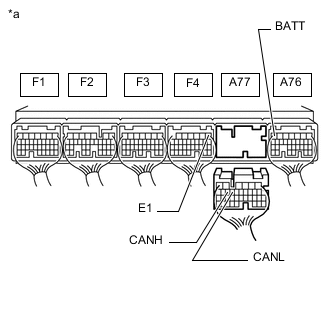
*a Rear view of wire harness connector
(to ECM)
Disconnect the A77 ECM connector.
-
Measure the resistance according to the value(s) in the table below.
-
-
ECM (for 8AR-FTS)
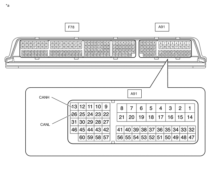
*a Component without harness connected
(ECM)
- -
-
Disconnect the cable from the negative (-) battery terminal.
-
Disconnect the A91 and F78 ECM connectors.
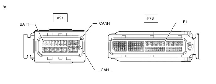
*a Front view of wire harness connector
(to ECM)
- - -
Measure the resistance according to the value(s) in the table below.
-
-
COMBINATION METER ASSEMBLY
-
Disconnect the cable from the negative (-) battery terminal.
-
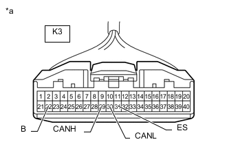
*a Front view of wire harness connector
(to Combination Meter Assembly)
Disconnect the K3 combination meter assembly connector.
-
Measure the resistance according to the value(s) in the table below.
-
-
INSTRUMENT PANEL JUNCTION BLOCK ASSEMBLY AND MAIN BODY ECU (MULTIPLEX NETWORK BODY ECU)
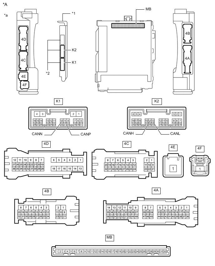
*A Main Body ECU (Multiplex Network Body ECU) with 3 Connectors - - *1 Main Body ECU (Multiplex Network Body ECU) *2 3 Connectors *a Component without harness connected
(Instrument Panel Junction Block Assembly and Main Body ECU (Multiplex Network Body ECU))
- -
-
Disconnect the cable from the negative (-) battery terminal.
-
Disconnect the K1 or K2 main body ECU (multiplex network body ECU) connector.
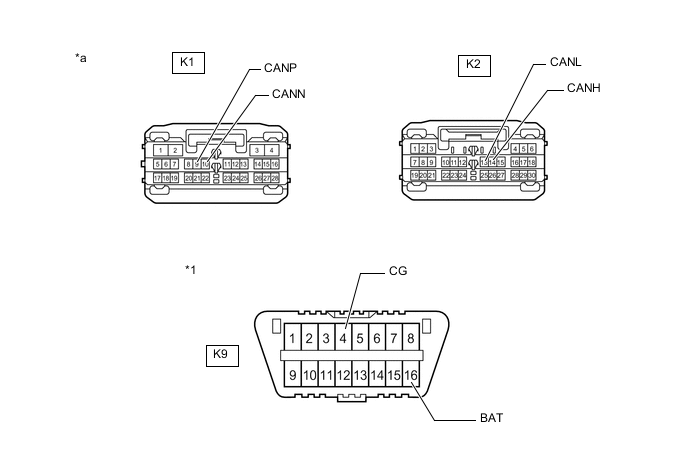
*1 DLC3 - - *a Front view of wire harness connector
(to Main Body ECU (Multiplex Network Body ECU))
- - -
Measure the resistance according to the value(s) in the table below.
-
-
SKID CONTROL ECU (BRAKE ACTUATOR ASSEMBLY)
-
Disconnect the cable from the negative (-) battery terminal.
-
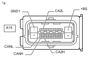
*a Front view of wire harness connector
(to Skid Control ECU (Brake Actuator Assembly))
Disconnect the A15 skid control ECU (brake actuator assembly) connector.
-
Measure the resistance according to the value(s) in the table below.
-
-
STEERING SENSOR
-
Disconnect the cable from the negative (-) battery terminal.
-
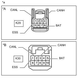
*A w/o VGRS System *B w/ VGRS System *a Front view of wire harness connector
(to Steering Sensor)
Disconnect the K29*1 or K30*2 steering sensor connector.
-
*1: w/o VGRS System
-
*2: w/ VGRS System
-
-
Measure the resistance according to the value(s) in the table below.
-
-
YAW RATE SENSOR
-
Disconnect the cable from the negative (-) battery terminal.
-
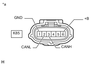
*a Front view of wire harness connector
(to Yaw Rate Sensor)
Disconnect the K85 yaw rate sensor connector.
-
Measure the resistance according to the value(s) in the table below.
-
-
POWER STEERING ECU ASSEMBLY
-
Disconnect the cable from the negative (-) battery terminal.
-
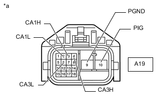
*a Front view of wire harness connector
(to Power Steering ECU Assembly)
Disconnect the A19 power steering ECU assembly connector.
-
Measure the resistance according to the value(s) in the table below.
-
-
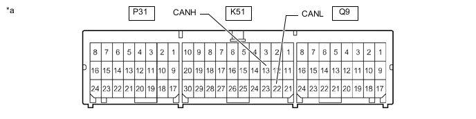
AIRBAG SENSOR ASSEMBLY
*a Component without harness connected
(Airbag Sensor Assembly)
- -
-
Disconnect the cable from the negative (-) battery terminal.
-
Disconnect the K51 airbag sensor assembly connector.
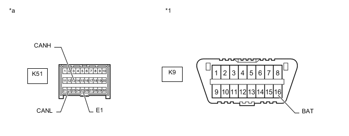
*1 DLC3 - - *a Front view of wire harness connector
(to Airbag Sensor Assembly)
- - -
Measure the resistance according to the value(s) in the table below.
-
-
CERTIFICATION ECU (SMART KEY ECU ASSEMBLY)
-
Disconnect the cable from the negative (-) battery terminal.
-
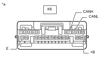
*a Front view of wire harness connector
(to Certification ECU (Smart Key ECU Assembly))
Disconnect the K6 certification ECU (smart key ECU assembly) connector.
-
Measure the resistance according to the value(s) in the table below.
-
-
RADIO RECEIVER ASSEMBLY (w/ Navigation System)
-
Disconnect the cable from the negative (-) battery terminal.
-
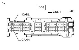
*a Front view of wire harness connector
(to Radio Receiver Assembly)
Disconnect the K58 radio receiver assembly connector.
-
Measure the resistance according to the value(s) in the table below.
-
-
RADIO RECEIVER ASSEMBLY (w/ Radio and Display Type with Parallel Parking Assist Function)
-
Disconnect the cable from the negative (-) battery terminal.
-
*a Front view of wire harness connector
(to Radio Receiver Assembly)
Disconnect the K58 radio receiver assembly connector.
-
Measure the resistance according to the value(s) in the table below.
-
-
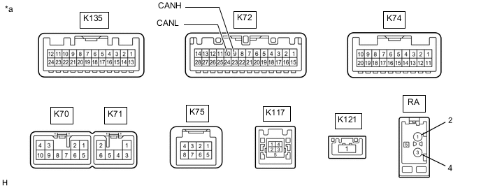
RADIO RECEIVER ASSEMBLY (w/ Radio and Display Type without Parallel Parking Assist Function)
*a Component without harness connected
(Radio Receiver Assembly)
- -
-
Disconnect the cable from the negative (-) battery terminal.
-
Disconnect the K70 and K72 radio receiver assembly connectors.
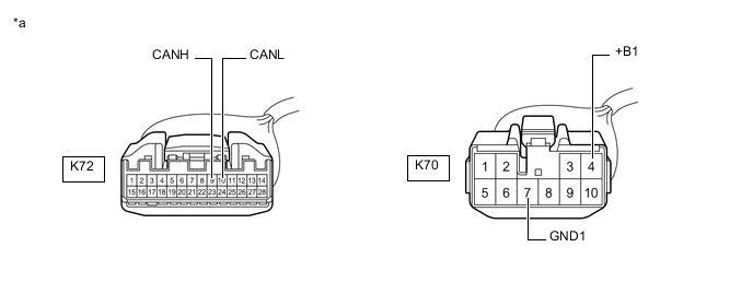
*a Front view of wire harness connector
(to Radio Receiver Assembly)
- - -
Measure the resistance according to the value(s) in the table below.
-
-
AIR CONDITIONING AMPLIFIER ASSEMBLY
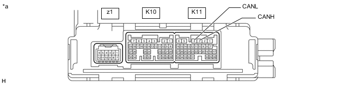
*a Component without harness connected
(Air Conditioning Amplifier Assembly)
- -
-
Disconnect the cable from the negative (-) battery terminal.
-
Disconnect the K10 and K11 air conditioning amplifier assembly connectors.
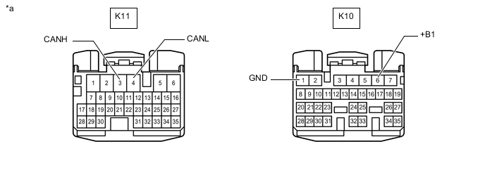
*a Front view of wire harness connector
(to Air Conditioning Amplifier Assembly)
- - -
Measure the resistance according to the value(s) in the table below.
-
-
NETWORK GATEWAY ECU (w/ Network Gateway ECU)
-
Disconnect the cable from the negative (-) battery terminal.
-
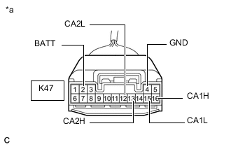
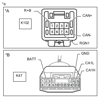
*a Front view of wire harness connector
(to Network Gateway ECU)
Disconnect the K47 network gateway ECU connector.
-
Measure the resistance according to the value(s) in the table below.
-
-
TELEMATICS TRANSCEIVER (w/ Telematics Transceiver)
-
Disconnect the cable from the negative (-) battery terminal.
-
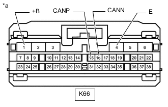
*a Front view of wire harness connector
(to Telematics Transceiver)
Disconnect the K66 telematics transceiver connector.
-
Measure the resistance according to the value(s) in the table below.
-
-
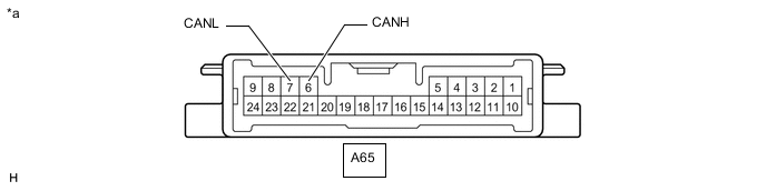
HEADLIGHT LEVELING ECU ASSEMBLY
*a Component without harness connected
(Headlight Leveling ECU Assembly)
- -
-
Disconnect the cable from the negative (-) battery terminal.
-
Disconnect the A65 headlight leveling ECU assembly connector.
*1 DLC3 - - *a Front view of wire harness connector
(to Headlight Leveling ECU Assembly)
- - -
Measure the resistance according to the value(s) in the table below.
-
-
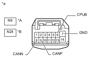
OUTER MIRROR CONTROL ECU ASSEMBLY (for Driver Side with Seat Position Memory System)
-
Disconnect the cable from the negative (-) battery terminal.
-
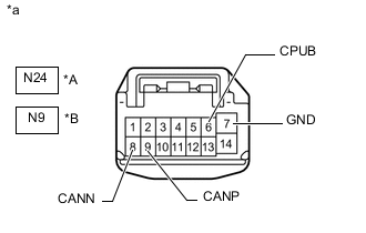
*A for LHD *B for RHD *a Front view of wire harness connector
(to Outer Mirror Control ECU Assembly (for Driver Side))
Disconnect the N24 or N9 outer mirror control ECU assembly (for driver side) connector.
-
Measure the resistance according to the value(s) in the table below.
-
-
OUTER MIRROR CONTROL ECU ASSEMBLY (for Front Passenger Side with Seat Position Memory System)
-
Disconnect the cable from the negative (-) battery terminal.
-
*A for LHD *B for RHD *a Front view of wire harness connector
(to Outer Mirror Control ECU Assembly (for Front Passenger Side))
Disconnect the N9 or N24 outer mirror control ECU assembly (for front passenger side) connector.
-
Measure the resistance according to the value(s) in the table below.
-
-
FRONT POWER SEAT SWITCH LH (for LHD with Seat Position Memory System)

*a Component without harness connected
(Front Power Seat Switch LH)
- -
-
Disconnect the cable from the negative (-) battery terminal.
-
Disconnect the b11 and b12 front power seat switch LH connectors.
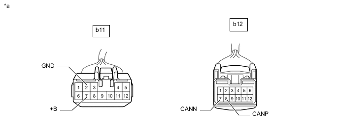
*a Front view of wire harness connector
(to Front Power Seat Switch LH)
- - -
Measure the resistance according to the value(s) in the table below.
-
-
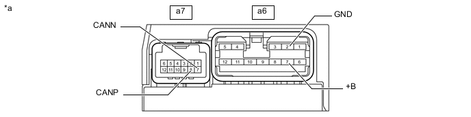
FRONT POWER SEAT SWITCH RH (for RHD with Seat Position Memory System)
*a Component without harness connected
(Front Power Seat Switch RH)
- -
-
Disconnect the cable from the negative (-) battery terminal.
-
Disconnect the a6 and a7 front power seat switch RH connectors.
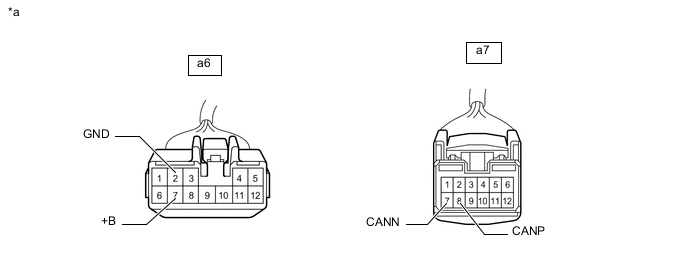
*a Front view of wire harness connector
(to Front Power Seat Switch RH)
- - -
Measure the resistance according to the value(s) in the table below.
-
-
MULTIPLEX TILT AND TELESCOPIC ECU (w/ Power Tilt and Power Telescopic System)
-
Disconnect the cable from the negative (-) battery terminal.
-
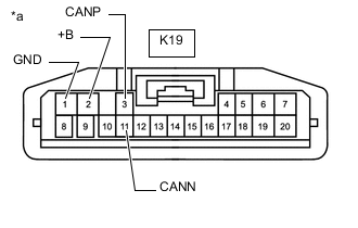
*a Front view of wire harness connector
(to Multiplex Tilt and Telescopic ECU)
Disconnect the K19 multiplex tilt and telescopic ECU connector.
-
Measure the resistance according to the value(s) in the table below.
-
-
FRONT STEERING CONTROL ECU (w/ VGRS System)
-
Disconnect the cable from the negative (-) battery terminal.
-
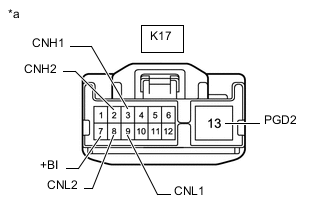
*a Front view of wire harness connector
(to Front Steering Control ECU)
Disconnect the K17 front steering control ECU connector.
-
Measure the resistance according to the value(s) in the table below.
-
-
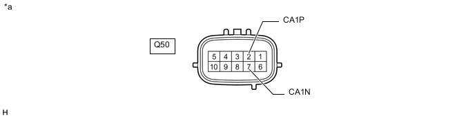
BLIND SPOT MONITOR SENSOR LH (w/ Blind Spot Monitor System)
*a Component without harness connected
(Blind Spot Monitor Sensor LH)
- -
-
Disconnect the cable from the negative (-) battery terminal.
-
Disconnect the Q50 blind spot monitor sensor LH connector.
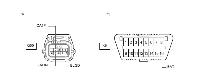
*1 DLC3 - - *a Front view of wire harness connector
(to Blind Spot Monitor Sensor LH)
- - -
Measure the resistance according to the value(s) in the table below.
-
-
DRIVING SUPPORT ECU ASSEMBLY (w/ Pre-crash Safety System)
-
Disconnect the cable from the negative (-) battery terminal.
-
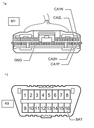
*1 DLC3 *a Front view of wire harness connector
(to Driving Support ECU Assembly)
Disconnect the M1 driving support ECU assembly connector.
-
Measure the resistance according to the value(s) in the table below.
-
-
MILLIMETER WAVE RADAR SENSOR ASSEMBLY (w/ Pre-crash Safety System)
-
Disconnect the cable from the negative (-) battery terminal.
-
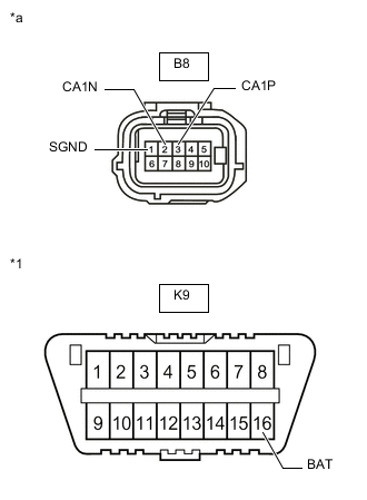
*1 DLC3 *a Front view of wire harness connector
(to Millimeter Wave Radar Sensor Assembly)
Disconnect the B8 millimeter wave radar sensor assembly connector.
-
Measure the resistance according to the value(s) in the table below.
-
-
OPTION CONNECTOR (BUS BUFFER ECU)
-
Disconnect the cable from the negative (-) battery terminal.
-
*A w/ Network Gateway ECU and Option Connector *B w/o Network Gateway ECU *a Front view of wire harness connector
(to Option Connector (Bus buffer ECU))
Measure the resistance according to the value(s) in the table below.
-
-
CLEARANCE WARNING ECU ASSEMBLY (w/ LEXUS Parking Assist-sensor System)
-
Disconnect the cable from the negative (-) battery terminal.
-
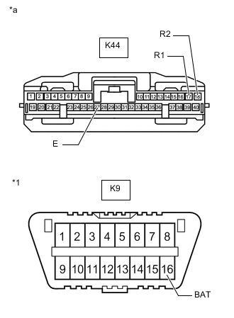
*1 DLC3 *a Front view of wire harness connector
(to Clearance Warning ECU Assembly)
Disconnect the K44 clearance warning ECU assembly connector.
-
Measure the resistance according to the value(s) in the table below.
-
-
LANE DEPARTURE WARNING CAMERA (w/ Lane Departure Alert System)
-
Disconnect the cable from the negative (-) battery terminal.
-
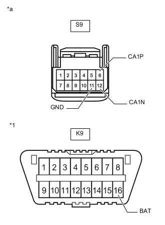
*1 DLC3 *a Front view of wire harness connector
(to Lane Departure Warning Camera)
Disconnect the S9 lane departure warning camera connector.
-
Measure the resistance according to the value(s) in the table below.
-
-
ABSORBER CONTROL ECU (w/ AVS System)
-
Disconnect the cable from the negative (-) battery terminal.
-
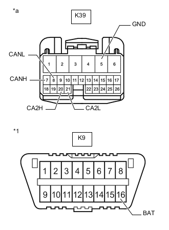
*1 DLC3 *a Front view of wire harness connector
(to Absorber Control ECU)
Disconnect the K39 absorber control ECU connector.
-
Measure the resistance according to the value(s) in the table below.
-
-
ENGINE STOP AND START ECU (w/ Stop and Start System)
-
Disconnect the cable from the negative (-) battery terminal.
-
Disconnect the A93 and K139 engine stop and start ECU connectors.
-
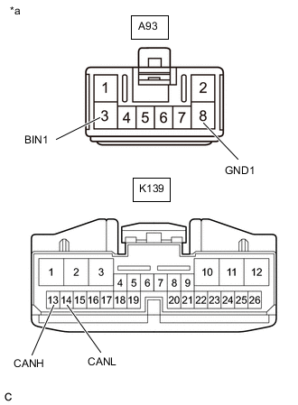
*a Front view of wire harness connector
(to Engine Stop and Start ECU)
Measure the resistance according to the value(s) in the table below.
-
-
REAR TELEVISION CAMERA ASSEMBLY (w/ Parking Assist Monitor System without Parallel Parking Assist Function)

*a Component without harness connected
(Rear Television Camera Assembly)
- -
-
Disconnect the cable from the negative (-) battery terminal.
-
Disconnect the T2 rear television camera assembly connector.
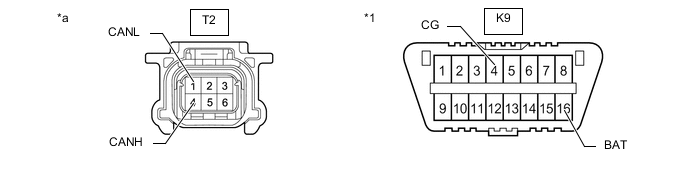
*1 DLC3 - - *a Front view of wire harness connector
(to Rear Television Camera Assembly)
- - -
Measure the resistance according to the value(s) in the table below.
-