G-BOOK SYSTEM(w/ Telematics Transceiver) Emergency Call Switch Indicator Circuit
WIRING DIAGRAM
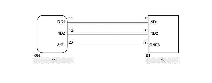
| *1 | Telematics Transceiver |
| *2 | Map Light Assembly |
CAUTION / NOTICE / HINT
Note
Depending on the parts that are replaced during vehicle inspection or maintenance, performing initialization, registration or calibration may be needed. Refer to Precaution for G-BOOK.
PROCEDURE
-
CHECK HARNESS AND CONNECTOR (TELEMATICS TRANSCEIVER - MAP LIGHT ASSEMBLY)
-
Disconnect the K66 telematics transceiver connector.
-
Disconnect the S4 map light assembly connector.
-
Measure the resistance according to the value(s) in the table below.
Standard Resistance Tester Connection Condition Specified Condition K66-11 (IND1) - S4-6 (IND1) Always Below 1 Ω K66-12 (IND2) - S4-7 (IND2) Always Below 1 Ω K66-26 (SIG-) - S4-9 (GND3) Always Below 1 Ω K66-11 (IND1) - Body ground Always 10 kΩ or higher K66-12 (IND2) - Body ground Always 10 kΩ or higher K66-26 (SIG-) - Body ground Always 10 kΩ or higher Result Proceed to OK NG
NG 
REPAIR OR REPLACE HARNESS OR CONNECTOR
OK 
-
-
INSPECT MAP LIGHT ASSEMBLY
-
Remove the map light assembly.
-
Connect 2 1.5 V dry-cell batteries in series.
-
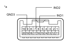
*a Component without harness connected
(Map Light Assembly)
Connect a positive (+) lead from the batteries to terminal 6 (IND1) or 7 (IND2), and a negative (-) lead to terminal 9 (GND3) of the map light assembly connector.
-
Check if the illumination for the emergency call switch comes on.
OK The red indicator light on the emergency call switch comes on when the positive (+) lead from the batteries is connected to terminal 6 (IND1) and the negative (-) lead is connected to terminal 9 (GND3). The green indicator light on the emergency call switch comes on when the positive (+) lead from the batteries is connected to terminal 7 (IND2) and the negative (-) lead is connected to terminal 9 (GND3). Result Proceed to OK NG
OK
REPLACE TELEMATICS TRANSCEIVER Click here
NG
REPLACE MAP LIGHT ASSEMBLY Click here
-