STEERING COLUMN ASSEMBLY INSTALLATION
PROCEDURE
-
INSTALL STEERING SLIDING YOKE SUB-ASSEMBLY
-
w/o VGRS:
-
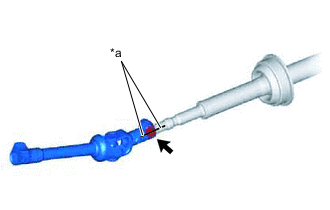
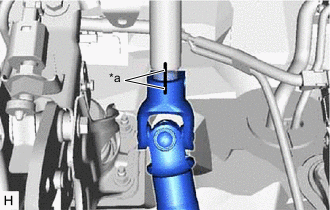
*a Matchmark Connect the steering sliding yoke sub-assembly to the No. 2 steering intermediate shaft assembly.
Note
Align the matchmarks on the steering sliding yoke sub-assembly and No. 2 steering intermediate shaft assembly.
-
Temporarily install the bolt.
-
-
w/ VGRS:
-
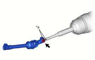
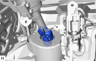
*a Matchmark Connect the steering sliding yoke sub-assembly to the steering actuator assembly.
Note
Align the matchmarks on the steering sliding yoke sub-assembly and steering actuator assembly.
-
Temporarily install the bolt.
-
-
-
ALIGN FRONT WHEELS FACING STRAIGHT AHEAD
-
INSTALL NO. 2 STEERING INTERMEDIATE SHAFT ASSEMBLY (w/o VGRS)
-
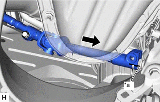
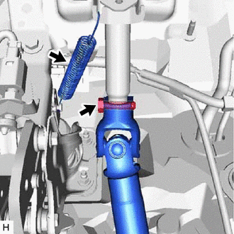
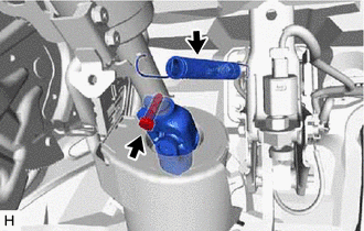
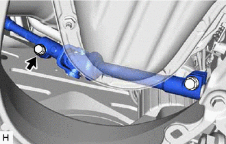
*a Matchmark Install the steering sliding yoke sub-assembly to the power steering link assembly.
Note
Align the matchmarks on the steering sliding yoke sub-assembly and power steering link assembly.
-
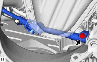
Install the bolt.
- Torque:
- 35.3 N*m { 360 kgf*cm, 26 ft.*lbf }
-
Tighten the clamp.
-
-
INSTALL STEERING ACTUATOR ASSEMBLY (w/ VGRS)
-
INSTALL LOWER MAIN SHAFT DUST COVER (w/ VGRS)
-
INSTALL STEERING COLUMN ASSEMBLY
-
w/o VGRS:
-
*a Matchmark Install the steering column assembly to the No. 2 steering intermediate shaft assembly.
Note
Align the matchmarks on the steering column assembly and No. 2 steering intermediate shaft assembly.
-
-
w/ VGRS:
-
*a Matchmark Install the steering column assembly to the steering actuator assembly.
Note
Align the matchmarks on the steering column assembly and steering actuator assembly.
-
-
Install the steering column assembly with the 4 nuts.
- Torque:
- for Manual Tilt and Manual Telescopic Steering Column
- 21 N*m { 214 kgf*cm, 15 ft.*lbf }
- for Power Tilt and Power Telescopic Steering Column
- 25.5 N*m { 260 kgf*cm, 19 ft.*lbf }
-
w/o VGRS:
-
Install the bolt.
- Torque:
- 35.3 N*m { 360 kgf*cm, 26 ft.*lbf }
-
Install the brake pedal return spring to the push rod pin and steering column assembly.
-
-
w/ VGRS:
-
Install the bolt.
- Torque:
- 35.3 N*m { 360 kgf*cm, 26 ft.*lbf }
-
Install the brake pedal return spring to the push rod pin and steering column assembly.
-
-
Connect each connector and engage each wire harness clamp to the steering column assembly.
-
Fully tighten the bolt.
- Torque:
- 35.3 N*m { 360 kgf*cm, 26 ft.*lbf }
-
-
INSTALL NO. 2 ENGINE UNDER COVER
for 8AR-FTS: Click here
for 2GR-FKS: Click here
-
INSTALL FRONT SUSPENSION MEMBER BRACE
for 8AR-FTS: Click here
for 2GR-FKS: Click here
-
INSTALL AIR DUCT SUB-ASSEMBLY
-
Install the air duct sub-assembly with the bolt.
- Torque:
- 9.8 N*m { 100 kgf*cm, 87 in.*lbf }
-
-
INSTALL LOWER NO. 1 INSTRUMENT PANEL AIRBAG ASSEMBLY
-
INSTALL TURN SIGNAL SWITCH ASSEMBLY WITH SPIRAL CABLE SUB-ASSEMBLY
Note
-
Do not replace the spiral cable with sensor sub-assembly with the battery connected and the engine switch on (IG).
-
Do not rotate the spiral cable with sensor sub-assembly without the steering wheel assembly with the battery connected and the engine switch on (IG).
-
Ensure that the steering wheel assembly is installed and aligned straight when inspecting the steering sensor.
-
Engage the 3 claws to install the turn signal switch assembly with spiral cable sub-assembly to the steering column assembly.
-
Connect the each connector to the turn signal switch assembly with spiral cable sub-assembly.
-
-
INSTALL STEERING COLUMN COVER
-
Engage the 2 claws to install the steering column cover (upper).
-
Engage the 6 clips to the steering column cover (upper).
-
for Manual Tilt and Manual Telescopic Steering Column:
-
Engage the 3 claws to install the steering column cover (lower).
-
Install the 2 screws.
-
-
for Power Tilt and Power Telescopic Steering Column:
-
Engage the 2 claws to install the steering column cover (lower).
-
Install the 3 screws.
-
-
-
ALIGN FRONT WHEELS FACING STRAIGHT AHEAD
-
INSPECT AND ADJUST SPIRAL CABLE WITH SENSOR SUB-ASSEMBLY
-
INSTALL STEERING WHEEL ASSEMBLY (w/o Pre-collision System)
-
INSTALL STEERING WHEEL ASSEMBLY (w/ Pre-collision System)
-
CHECK STEERING WHEEL CENTER POINT
-
INSTALL HORN BUTTON ASSEMBLY
-
CUSTOMIZE POWER TILT AND POWER TELESCOPIC STEERING COLUMN SYSTEM (for Power Tilt and Power Telescopic Steering Column)
-
Reset the auto tilt away function setting to the previous condition by changing the customize parameter.
-
-
PERFORM VARIABLE GEAR RATIO STEERING SYSTEM CALIBRATION (w/ VGRS)
-
ADJUST PARKING ASSIST MONITOR SYSTEM (w/ Parking Assist Monitor System)
w/ Parallel Parking Assist Function: Click here
w/o Parallel Parking Assist Function: Click here