POWER STEERING ECU(for LHD) INSTALLATION
PROCEDURE
-
INSTALL POWER STEERING ECU ASSEMBLY
-
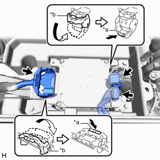
*a Lock of the Lock Lever *b Lock Lever Connect the 3 connectors to the power steering ECU assembly.
Tech Tips
When connecting the connector with lock lever, as shown in the illustration, return the lock lever to its original position to connect the connector and securely push in the lock of the lock lever.
-
Install the power steering ECU assembly to the battery tray with the 3 bolts.
- Torque:
- 8.5 N*m { 87 kgf*cm, 75 in.*lbf }
-
-
INSTALL NO. 1 BATTERY TRAY SUPPORT
-
Install the No. 1 battery tray support.
-
-
INSTALL BATTERY
-
Install the battery and battery insulator.
-
Connect the 2 harness clamps.
-
Install the battery clamp with the nut.
- Torque:
- 2.9 N*m { 30 kgf*cm, 26 in.*lbf }
-
Connect the cable to the positive (+) battery terminal and tighten the nut.
- Torque:
- 5.5 N*m { 56 kgf*cm, 49 in.*lbf }
-
Engage the 2 claws to install the center No. 1 cowl top ventilator louver.
-
-
CONNECT CABLE TO NEGATIVE BATTERY TERMINAL
-
Connect the cable to the negative (-) battery terminal and tighten the nut.
- Torque:
- 5.5 N*m { 56 kgf*cm, 49 in.*lbf }
Note
When disconnecting the cable, some systems need to be initialized after the cable is reconnected.
-
-
ROTATION ANGLE SENSOR INITIALIZATION AND TORQUE SENSOR ZERO POINT CALIBRATION
-
ASSIST MAP WRITING