REAR SUNSHADE SYSTEM Rear Sunshade Shift-linked Function does not Operate when Shift Lever is Moved to R Position
DESCRIPTION
When the engine switch is on (IG) and the shift lever is moved to R, the shift position sensors send a reverse signal to the ECM. Then, the ECM sends this signal to the main body ECU (multiplex network body ECU) via CAN communication. When the rear sunshade relay receives this signal with the rear sunshade raised, the rear sunshade is lowered.
WIRING DIAGRAM
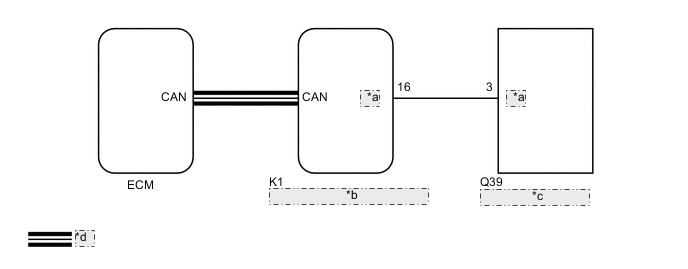
| *a | REV |
| *b | Main Body ECU (Multiplex Network Body ECU) |
| *c | Rear Sunshade Relay |
| *d | CAN Communication Line |
CAUTION / NOTICE / HINT
Note
-
The rear sunshade system uses the CAN communication system. First, confirm that there are no malfunctions in the CAN communication system. Refer to How to Proceed with Troubleshooting procedure.
-
The shift-linked operation of the rear sunshade system operates only when the customize setting "R-pos to Rear Sun Shade COM" is set to "ON".
-
If the main body ECU (multiplex network body ECU) is replaced, refer to Service Bulletin.
PROCEDURE
-
READ VALUE USING GTS (SHIFT SW STATUS (R RANGE))
-
Connect the GTS to the DLC3.
-
Turn the engine switch on (IG).
-
Turn the GTS on.
-
Enter the following menus: Powertrain / Engine and ECT / Data List.
-
Read the Data List according to the display on the GTS.
Powertrain > Engine > Data ListTester Display Measurement Item Range Normal Condition Diagnostic Note Shift SW Status (R Range) PNP switch status ON or OFF ON: Shift lever in R
OFF: Shift lever not in R
When the shift lever position displayed on the GTS differs from the actual position, adjustment of the PNP switch or the shift cable may be incorrect.
Powertrain > Engine > Data ListTester Display Shift SW Status (R Range) OK The GTS display changes according to the shift position selected by using the shift lever. Result Proceed to OK NG
NG 
GO TO SFI SYSTEM for 2GR-FSE: Click here
GO TO SFI SYSTEM for 8AR-FTS (w/ Canister Pump Module): Click here
GO TO SFI SYSTEM for 8AR-FTS (w/o Canister Pump Module): Click hereOK 
-
-
PERFORM ACTIVE TEST USING GTS (REVERSE GEAR SIGNAL)
-
Connect the GTS to the DLC3.
-
Turn the engine switch on (IG).
-
Turn the GTS on.
-
Enter the following menus: Body Electrical / Main Body / Active Test.
-
Perform the Active Test according to the display on the GTS.
Tech Tips
Make sure that the rear window shade assembly is raised before performing the Active Test.
Body Electrical > Main Body > Active TestTester Display Measurement Item Control Range Diagnostic Note Reverse Gear Signal Reverse signal OFF/ON -
Body Electrical > Main Body > Active TestTester Display Reverse Gear Signal OK The rear window shade assembly is lowered. Result Proceed to OK NG
OK
REPLACE MAIN BODY ECU (MULTIPLEX NETWORK BODY ECU) Click here
NG
-
-
CHECK HARNESS AND CONNECTOR (REVERSE SIGNAL)
-
Disconnect the Q39 rear sunshade relay connector.
-
Measure the voltage according to the value(s) in the table below.
Standard Voltage Tester Connection Condition Specified Condition Q39-3 (REV) - Body ground Engine switch on (IG), shift lever in any position other than R → R 11 to 14 V → Below 1 V Result Proceed to OK NG
OK
REPLACE REAR SUNSHADE RELAY Click here
NG
-
-
CHECK HARNESS AND CONNECTOR (REAR SUNSHADE RELAY - MAIN BODY ECU (MULTIPLEX NETWORK BODY ECU))
-
Disconnect the K1 main body ECU (multiplex network body ECU) connector.
-
Measure the resistance according to the value(s) in the table below.
Standard Resistance Tester Connection Condition Specified Condition K1-16 (REV) - Q39-3 (REV) Always Below 1 Ω K1-16 (REV) - Body ground Always 10 kΩ or higher Q39-3 (REV) - Body ground Always 10 kΩ or higher Result Proceed to OK NG
OK
REPLACE MAIN BODY ECU (MULTIPLEX NETWORK BODY ECU) Click here
NG
REPAIR OR REPLACE HARNESS OR CONNECTOR
-