REAR SUNSHADE SYSTEM TERMINALS OF ECU
-
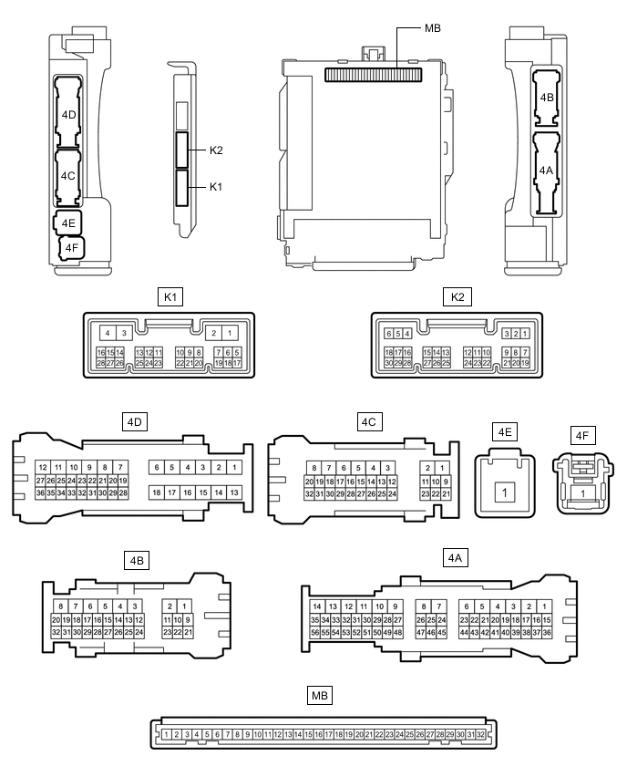
CHECK INSTRUMENT PANEL JUNCTION BLOCK ASSEMBLY AND MAIN BODY ECU (MULTIPLEX NETWORK BODY ECU)
-
Remove the main body ECU (multiplex network body ECU) from the instrument panel junction block assembly.
-
Reconnect the instrument panel junction block assembly connectors.
-
Measure the voltage and resistance according to the value(s) in the table below.
Tech Tips
Measure the values on the wire harness side with the connector disconnected.
Tester Connection Wiring Color Terminal Description Condition Specified Condition MB-11 (GND1) - Body ground - Ground Always Below 1 Ω MB-31 (BECU) - Body ground - Battery power supply Always 11 to 14 V MB-32 (IG) - Body ground - IG power supply Engine switch on (IG) 11 to 14 V MB-32 (IG) - Body ground - IG power supply Engine switch off Below 1 V MB-30 (ACC) - Body ground - ACC power supply Engine switch on (ACC) 11 to 14 V MB-30 (ACC) - Body ground - ACC power supply Engine switch off Below 1 V If the result is not as specified, there may be a malfunction in the wire harness.
-
Install the main body ECU (multiplex network body ECU) to the instrument panel junction block assembly.
-
Measure the voltage according to the value(s) in the table below.
Tester Connection Wiring Color Terminal Description Condition Specified Condition K1-16 (REV) - Body ground R - Body ground Reverse signal Engine switch on (IG), shift lever in any position other than R 11 to 14 V K1-16 (REV) - Body ground R - Body ground Reverse signal Engine switch on (IG), shift lever in R Below 1 V If the result is not as specified, the main body ECU (multiplex network body ECU) may be malfunctioning.
-
-
CHECK REAR SUNSHADE RELAY
-
Disconnect the Q39 rear sunshade relay connector.

-
Measure the voltage and resistance according to the value(s) in the table below.
Tech Tips
Measure the values on the wire harness side with the connector disconnected.
Tester Connection Wiring Color Terminal Description Condition Specified Condition Q39-8 (B) - Body ground B - Body ground Battery power supply Always 11 to 14 V Q39-7 (IG) - Body ground B - Body ground IG power supply Engine switch off Below 1 V Q39-7 (IG) - Body ground B - Body ground IG power supply Engine switch on (IG) 11 to 14 V Q39-1 (E) - Body ground W-B - Body ground Ground Always Below 1 Ω If the result is not as specified, there may be a malfunction in the wire harness.
-
Reconnect the Q39 rear sunshade relay connector.
-
Measure the voltage according to the value(s) in the table below.
Tester Connection Wiring Color Terminal Description Condition Specified Condition Q39-3 (REV) - Q39-1 (E) R - W-B Reverse signal Engine switch on (IG), shift lever in any position other than R 11 to 14 V Q39-3 (REV) - Q39-1 (E) R - W-B Reverse signal Engine switch on (IG), shift lever in R Below 1 V Q39-5 (SW) - Q39-1 (E) L - W-B Rear sunshade switch assembly signal Engine switch on (IG), rear sunshade switch assembly not pushed 11 to 14 V Q39-5 (SW) - Q39-1 (E) L - W-B Rear sunshade switch assembly signal Engine switch on (IG), rear sunshade switch assembly pushed and held Below 1 V If the result is not as specified, the rear sunshade relay may be malfunctioning.
-