COMPRESSOR INSTALLATION

PROCEDURE
-
ADJUST COMPRESSOR OIL
-
When replacing the compressor with a new one:
-
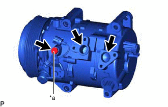
*a Drain Bolt (Washer) Remove the drain bolt (washer).
-
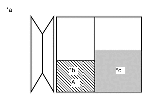
*a Removed Compressor *b Amount of oil to be drained from removed compressor *c Amount of oil remaining in the reserve chamber (60 cc (2.03 fl.oz)) Gradually discharge the inert gas from the service valve. Then drain the following amount of oil from the new compressor before installation so that the amount of oil contained in it is the same as that in the compressor to be replaced.
Tech Tips
New compressors are filled with sufficient oil for the whole air conditioning system. Therefore, it is necessary to drain oil from the new compressor to compensate for oil remaining in the condenser and cooling unit.
Standard (The amount of compressor oil inside a new compressor and magnetic clutch: 70 (+15) cc (2.37 (+0.51) fl.oz)) - (The amount of compressor oil remaining in the removed compressor and magnetic clutch) = The amount of compressor oil to be removed when replacing the compressor and magnetic clutch Note
-
When A + 60 cc (2.03 fl.oz) exceeds the standard oil fill volume specified for the compressor by part number, install the compressor without adjusting the oil volume.
Example:
If A = 45 cc (1.52 fl.oz), A + 60 cc (2.03 fl.oz) = 105 cc (3.55 fl.oz). If the standard volume is 100 cc (3.38 fl.oz), install the compressor as is.
-
If the amount of oil remaining in the removed compressor is too low, check for oil leaks.
-
Use ND-OIL 8 or equivalent for compressor oil.
-
for HFC-134a(R134a): Make sure to use ND-OIL 8 or equivalent compressor oil.
-
for HFO-1234yf(R1234yf): Make sure to use ND-OIL 12 or equivalent compressor oil.
-
-
Install the drain bolt (washer).
- Torque:
- 30 N*m { 306 kgf*cm, 22 ft.*lbf }
-
-
If draining the oil is difficult, drain the oil using the following procedure:
-
Remove the suction seal cap.
-
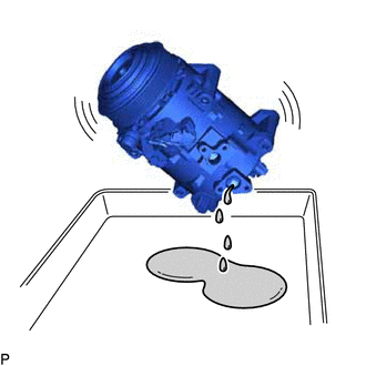
Lightly shake the compressor with the suction port facing down, and drain the oil (*1).
Note
Do not allow the pulley to come into contact with the compressor oil.
-
-
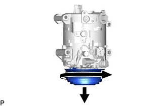
With the pulley facing down, rotate the hub as shown in the illustration 10 times at a rate of approximately once every 2 seconds (*2).
CAUTION:
If the pulley is rotated, refrigerant or oil may spray out. Thus, keep your face away from the compressor port.
-
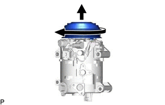
Rotate the hub once as shown in the illustration while quickly turning the compressor with the pulley facing up (*3).
-
Perform step (*1) and drain the oil (*4).
-
Drain the oil by repeating steps (*2) to (*4) approximately 5 times.
-
-
INSTALL COMPRESSOR AND MAGNETIC CLUTCH (for 2GR-FKS)
-
for Type A:
-
Using an E8 "TORX" socket wrench, temporarily install the compressor and magnetic clutch with the stud bolt.
-
Tighten the stud bolt.
- Torque:
- 10 N*m { 102 kgf*cm, 7 ft.*lbf }
-
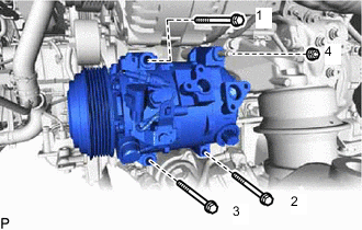
Install the compressor and magnetic clutch with the 3 bolts and nut.
- Torque:
- Bolt
- 24.5 N*m { 250 kgf*cm, 18 ft.*lbf }
- Nut
- 24.5 N*m { 250 kgf*cm, 18 ft.*lbf }
Tech Tips
Tighten the bolts and nut in the order shown in the illustration.
-
-
for Type B:
-
Using an E8 "TORX" socket wrench, temporarily install the compressor and magnetic clutch with the stud bolt.
-
Tighten the stud bolt.
- Torque:
- 10 N*m { 102 kgf*cm, 7 ft.*lbf }
-
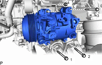
Install the compressor and magnetic clutch with the 3 bolts and nut.
- Torque:
- Bolt
- 24.5 N*m { 250 kgf*cm, 18 ft.*lbf }
- Nut
- 24.5 N*m { 250 kgf*cm, 18 ft.*lbf }
Tech Tips
Tighten the bolts and nut in the order shown in the illustration.
-
-
Engage the clamp.
-
Connect the 2 connectors.
-
-
INSTALL COMPRESSOR AND MAGNETIC CLUTCH (for 8AR-FTS)
-
Using an E8 "TORX" socket wrench, temporarily install the compressor and magnetic clutch with the 2 stud bolts.
-
Tighten the 2 stud bolts.
- Torque:
- 10 N*m { 102 kgf*cm, 7 ft.*lbf }
-
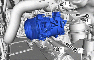
Install the compressor and magnetic clutch with the 2 bolts and 2 nuts.
- Torque:
- Bolt
- 24.5 N*m { 250 kgf*cm, 18 ft.*lbf }
- Nut
- 24.5 N*m { 250 kgf*cm, 18 ft.*lbf }
Tech Tips
Tighten the bolts and nuts in the order shown in the illustration.
-
Engage the clamp.
-
Connect the 2 connectors.
-
-
CONNECT SUCTION HOSE (for 2GR-FKS)
-
Remove the vinyl tape from the suction hose and compressor and magnetic clutch.
-
Sufficiently apply compressor oil to a new O-ring and the fitting surface of the compressor and magnetic clutch.
Compressor Oil ND-OIL 8 or equivalent -
Install the O-ring to the suction hose.
-
Connect the suction hose to the compressor and magnetic clutch with the bolt.
- Torque:
- 9.8 N*m { 100 kgf*cm, 87 in.*lbf }
-
-
CONNECT SUCTION HOSE (for 8AR-FTS)
-
Remove the vinyl tape from the suction hose and compressor and magnetic clutch.
-
Sufficiently apply compressor oil to a new O-ring and the fitting surface of the compressor and magnetic clutch.
Refrigerant Compressor Oil HFC-134a (R134a) ND-OIL 8 or equivalent HFO-1234yf (R1234yf) ND-OIL 12 or equivalent -
Install the O-ring to the suction hose.
-
Connect the suction hose to the compressor and magnetic clutch with the bolt.
- Torque:
- 9.8 N*m { 100 kgf*cm, 87 in.*lbf }
-
-
CONNECT NO. 1 COOLER REFRIGERANT DISCHARGE HOSE (for 2GR-FKS)
-
Remove the vinyl tape from the No. 1 cooler refrigerant discharge hose and compressor and magnetic clutch.
-
Sufficiently apply compressor oil to a new O-ring and the fitting surface of the compressor and magnetic clutch.
Compressor Oil ND-OIL 8 or equivalent -
Install the O-ring to the No. 1 cooler refrigerant discharge hose.
-
Connect the No. 1 cooler refrigerant discharge hose to the compressor and magnetic clutch with the bolt.
- Torque:
- 9.8 N*m { 100 kgf*cm, 87 in.*lbf }
-
-
CONNECT NO. 1 COOLER REFRIGERANT DISCHARGE HOSE (for 8AR-FTS)
-
Remove the vinyl tape from the No. 1 cooler refrigerant discharge hose and compressor and magnetic clutch.
-
Sufficiently apply compressor oil to a new O-ring and the fitting surface of the compressor and magnetic clutch.
Refrigerant Compressor Oil HFC-134a (R134a) ND-OIL 8 or equivalent HFO-1234yf (R1234yf) ND-OIL 12 or equivalent -
Install the O-ring to the No. 1 cooler refrigerant discharge hose.
-
Connect the No. 1 cooler refrigerant discharge hose to the compressor and magnetic clutch with the bolt.
- Torque:
- 9.8 N*m { 100 kgf*cm, 87 in.*lbf }
-
-
INSTALL FAN AND GENERATOR V BELT
for 2GR-FKS:
for 8AR-FTS:
-
INSTALL REAR ENGINE UNDER COVER LH
for 2GR-FKS:
for 8AR-FTS:
-
INSTALL ENGINE UNDER COVER
for 2GR-FKS:
for 8AR-FTS:
-
CHARGE AIR CONDITIONING SYSTEM WITH REFRIGERANT (for HFC-134a(R134a))
-
CHARGE AIR CONDITIONING SYSTEM WITH REFRIGERANT (for HFO-1234yf(R1234yf))
-
WARM UP ENGINE (for HFC-134a(R134a))
-
WARM UP ENGINE (for HFO-1234yf(R1234yf))
-
INSPECT FOR REFRIGERANT LEAK (for HFC-134a(R134a))
-
INSPECT FOR REFRIGERANT LEAK (for HFO-1234yf(R1234yf))