AIR CONDITIONING UNIT REMOVAL
CAUTION / NOTICE / HINT
Tech Tips
If the air conditioning radiator damper servo sub-assembly is to be removed and installed or replaced, make sure to set the temperature setting to MAX COLD before turning the engine switch off and disconnecting the cable from the negative (-) battery terminal.
PROCEDURE
-
RECOVER REFRIGERANT FROM REFRIGERATION SYSTEM (for HFC-134a(R134a))
-
RECOVER REFRIGERANT FROM REFRIGERATION SYSTEM (for HFO-1234yf(R1234yf))
-
REMOVE WINDSHIELD WIPER MOTOR AND LINK ASSEMBLY
-
DISCONNECT OUTLET HEATER WATER HOSE A
-
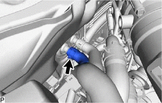
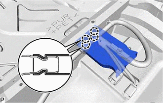
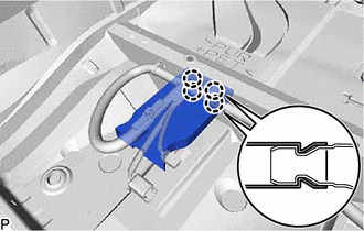
Using pliers, grip the claws of the clip and slide the clip to disconnect the outlet heater water hose A.
Note
-
Do not apply excessive force to the outlet heater water hose A.
-
Prepare a drain pan or cloth in case the coolant leaks.
-
-
-
DISCONNECT INLET HEATER WATER HOSE A
-
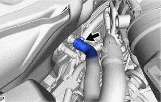
Using pliers, grip the claws of the clip and slide the clip to disconnect the inlet heater water hose A.
Note
-
Do not apply excessive force to the inlet heater water hose A.
-
Prepare a drain pan or cloth in case the coolant leaks.
-
-
-
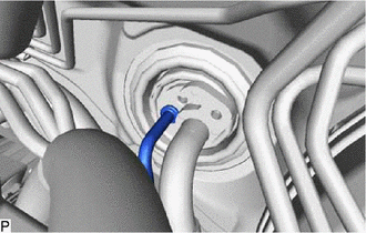
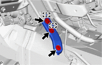
DISCONNECT SUCTION PIPE SUB-ASSEMBLY
-
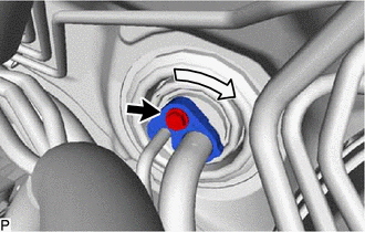
Remove the bolt and rotate the hook connector.
-
Disconnect the suction pipe sub-assembly.
-
Remove the O-ring from the suction pipe sub-assembly.
Note
Seal the openings of the disconnected parts using vinyl tape to prevent entry of moisture and foreign matter.
-
-
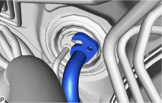
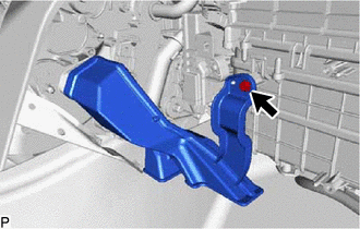
DISCONNECT COOLER REFRIGERANT LIQUID PIPE A
-
Disconnect the cooler refrigerant liquid pipe A.
-
Remove the O-ring from the cooler refrigerant liquid pipe A.
Note
Seal the openings of the disconnected parts using vinyl tape to prevent entry of moisture and foreign matter.
-
-
REMOVE FRONT SEAT ASSEMBLY LH (for Manual Seat)
-
REMOVE FRONT SEAT ASSEMBLY LH (for Power Seat)
-
REMOVE FRONT SEAT ASSEMBLY RH (for Manual Seat)
Tech Tips
Use the same procedure as for the LH side.
-
REMOVE FRONT SEAT ASSEMBLY RH (for Power Seat)
Tech Tips
Use the same procedure as for the LH side.
-
REMOVE INSTRUMENT PANEL SAFETY PAD SUB-ASSEMBLY
-
REMOVE STEERING COLUMN ASSEMBLY
-
REMOVE INSTRUMENT PANEL JUNCTION BLOCK ASSEMBLY WITH MAIN BODY ECU
for LHD:
for RHD:
-
REMOVE CLEARANCE WARNING ECU ASSEMBLY (w/ LEXUS Parking Assist-sensor System)
for LHD:
for RHD:
-
REMOVE DRIVING SUPPORT ECU ASSEMBLY (w/ Dynamic Radar Cruise Control System)
for LHD:
for RHD:
-
REMOVE ECU INTEGRATION BOX RH WITH ENGINE STOP AND START ECU (w/ Stop and Start System)
for LHD:
-
REMOVE ENGINE STOP AND START ECU (w/ Stop and Start System)
for RHD:
-
REMOVE ENGINE STOP AND START SOLENOID FILTER (w/ Stop and Start System)
-
REMOVE NO. 2 AIR DUCT SUB-ASSEMBLY
-
Remove the screw and No. 2 air duct sub-assembly.
-
-
REMOVE TIRE PRESSURE MONITOR INITIATOR DRIVER (w/ Tire Pressure Warning System)
-
REMOVE NETWORK GATEWAY ECU (w/ Network Gateway ECU)
-
REMOVE FRONT STEERING CONTROL ECU (w/ VGRS)
for LHD:
for RHD:
-
REMOVE ECO RUN VEHICLE CONVERTER ASSEMBLY (w/ Stop and Start System)
-
REMOVE AIR CONDITIONING AMPLIFIER ASSEMBLY
-
REMOVE COOLER (ROOM TEMP. SENSOR) THERMISTOR
-
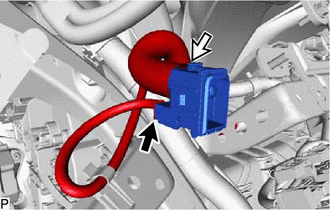
Disconnect the connector and air hose to remove the cooler (room temp. sensor) thermistor.
-
-
REMOVE ACCELERATOR PEDAL PAD
-
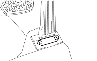
Disengage the 2 claws to remove the accelerator pedal pad.
-
-
REMOVE ACCELERATOR PEDAL ASSEMBLY
-
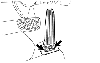
Remove the 2 bolts.
-
Remove the accelerator pedal assembly from the rod of the accelerator pedal sensor assembly.
-
-
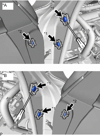
REMOVE FLOOR CARPET HOOK
-
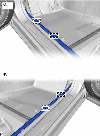
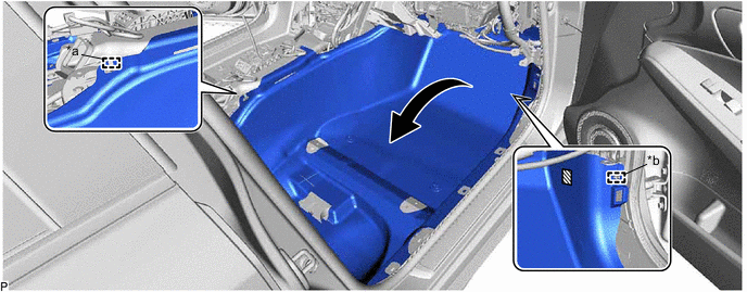
*A for LH Side *B for RH Side Disengage the 4 clamps and disconnect the wire harness.
-
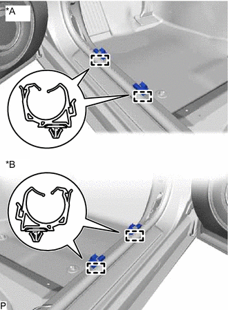
*A for LH Side *B for RH Side Disengage the 4 clamps to remove the 4 floor carpet hooks.
-
-
REMOVE REAR NO. 2 AIR DUCT
-
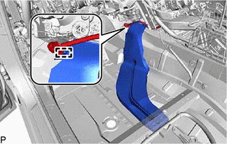
Using a clip remover, remove the clip.
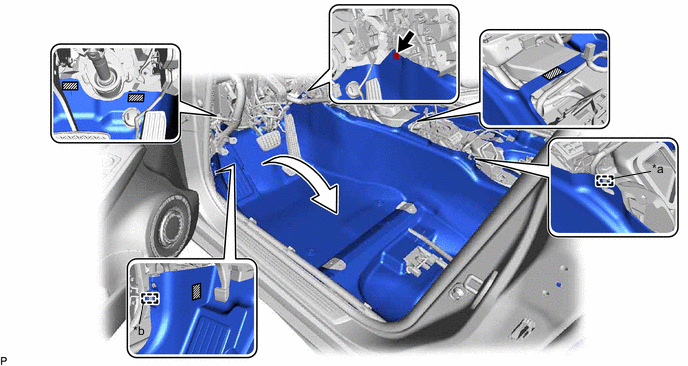
*a Guide *b Clamp 
Fastener - - -
Disengage the guide and clamp.
-
Disengage each fastener and turn back the front floor mat as shown in the illustration.
-
Disengage the 4 claws to remove the rear No. 2 air duct.
-
-
REMOVE FRONT FLOOR SILENCER PAD LH
-
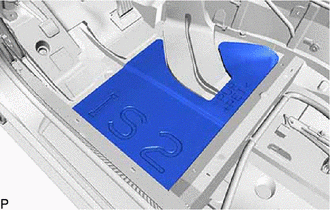
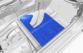
Remove the front floor silencer pad LH.
-
-
REMOVE REAR NO. 1 AIR DUCT
-
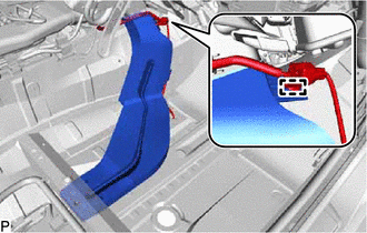
Disengage the clamp to disconnect the wire harness.
-
Remove the rear No. 1 air duct.
-
-
REMOVE REAR NO. 4 AIR DUCT
-
Disengage the guide and clamp.
*a Guide *b Clamp Fastener - - -
Disengage the fastener and turn back the front floor mat as shown in the illustration.
-
Disengage the 4 claws to remove the rear No. 4 air duct.
-
-
REMOVE FRONT FLOOR SILENCER PAD RH
-
Remove the front floor silencer pad RH.
-
-
REMOVE REAR NO. 3 AIR DUCT
-
Disengage the clamp to disconnect the wire harness.
-
Remove the rear No. 3 air duct.
-
-
REMOVE NO. 1 CONSOLE BOX DUCT
-
Disengage the 2 clamps.
-
Remove the 2 clips and No. 1 console box duct.
-
-
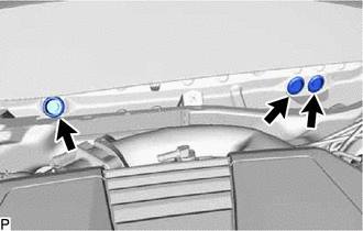
REMOVE NO. 2 INSTRUMENT PANEL TO FLOOR BRACE
-
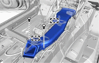
Remove the 3 bolts.
-
Disengage the 2 guides to remove the No. 2 instrument panel to floor brace.
-
-
REMOVE INSTRUMENT PANEL SAFETY PAD CAP
-
*A for LH Side *B for RH Side *1 Instrument Panel Safety Pad Cap (A) *2 Instrument Panel Safety Pad Cap (B) Protective Tape Put protective tape around the 6 instrument panel safety pad caps.
-
Using a screwdriver, remove the 4 instrument panel safety pad caps (A) and 2 instrument panel safety pad caps (B).
-
-
REMOVE INSTRUMENT PANEL REINFORCEMENT ASSEMBLY WITH AIR CONDITIONING UNIT
Note
-
Be sure to support the air conditioning unit assembly when removing it because failure to do so may cause the bracket of the air conditioning unit assembly to break.
-
When disassembling the air conditioning unit assembly, eliminate static electricity by touching the vehicle body to prevent the components from being damaged.
-
Remove the 3 bolts and disconnect the 3 earth wires.
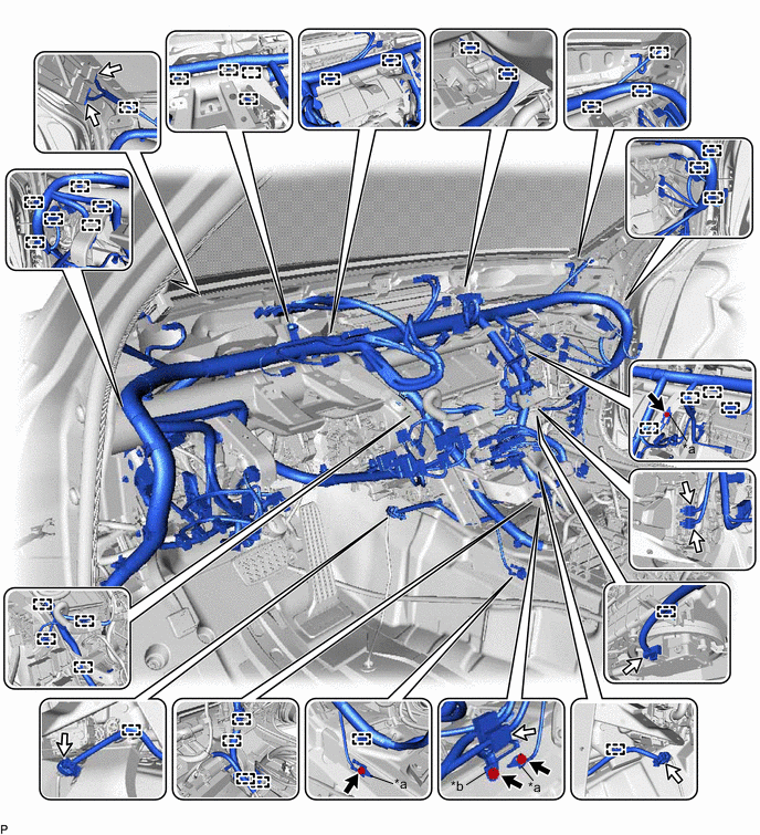
*a Earth Wire *b Bracket -
Remove the bolt and disconnect the bracket.
-
Disconnect each connector.
-
Disengage each clamp.
-
Remove the 3 hole plugs.
-
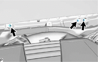
Remove the 3 bolts.
-
Remove the nut and 8 bolts as shown in the illustration.
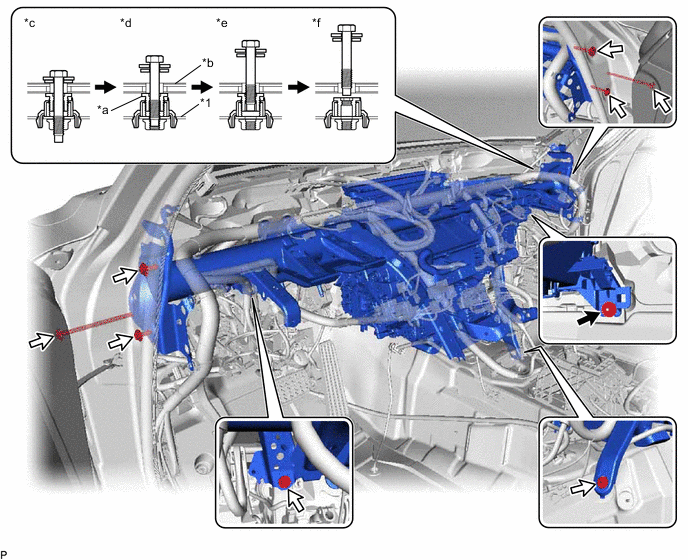
*1 Instrument Panel Reinforcement Assembly - - *a Movable Collar *b Vehicle Body *c Step 1 *d Step 2 *e Step 3 *f Step 4 
Nut 
Bolt -
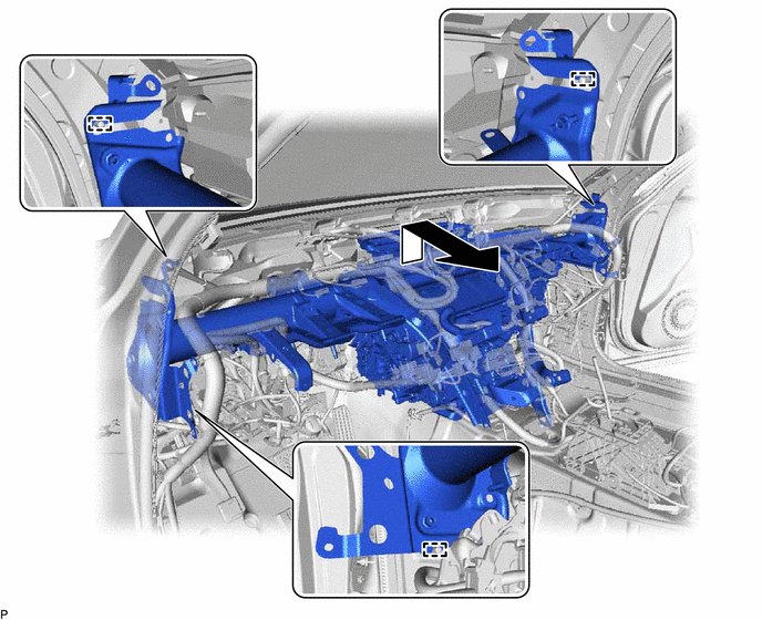
Disengage the 3 guides and remove the instrument panel reinforcement assembly with air conditioning unit as shown in the illustration.
-
-
REMOVE AIR CONDITIONING UNIT ASSEMBLY
-
Remove the 2 screws, 3 bolts and air conditioning unit assembly from the instrument panel reinforcement assembly.
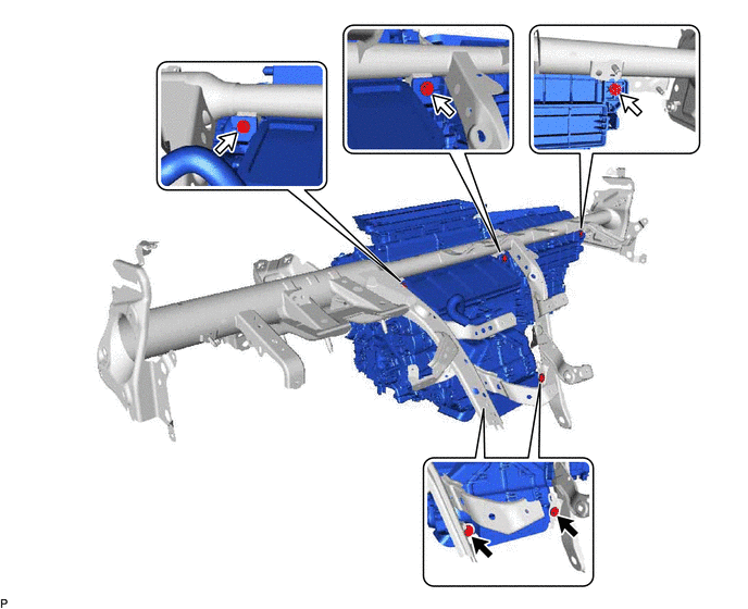
Screw Bolt
-