AIR CONDITIONING SYSTEM PTC Heater Circuit
DESCRIPTION
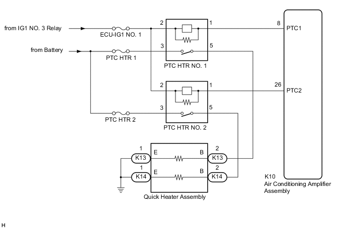
The air conditioning amplifier assembly sends operation signals to the PTC heater relays when quick heater assembly operation conditions are met. Based on the signals from the air conditioning amplifier assembly, the PTC heater relays turn on, and power is supplied to the quick heater assembly installed in the air conditioning radiator assembly.
| Control ECU | Condition |
|---|---|
| Air Conditioning Amplifier Assembly | Engine running |
| Combination switch assembly (ECO mode switch) off | |
| Blower switch: on | |
| Temperature settings: MAX HOT | |
| Light control switch assembly off | |
|
|
| Ambient temperature 3°C (37°F) or lower |
WIRING DIAGRAM
CAUTION / NOTICE / HINT
Note
-
Inspect the fuses for circuits related to this system before performing the following procedure.
-
If the battery voltage is low, the PTC heater may not operate. When "Operation of Electrical Items Restricted." is displayed on the multi-information display in the combination meter assembly, inspect the battery, referring to On-vehicle Inspection for the charging system.
for 2GR-FKS: Click here
for 8AR-FTS: Click here
-
If the battery voltage is low, the PTC heater may not operate. When "Operation of Electrical Items Restricted." is not displayed on the multi-information display in the combination meter assembly, check the Data List item "Battery Control Count (Body ECU)".
PROCEDURE
-
PERFORM ACTIVE TEST USING GTS
-
Connect the GTS to the DLC3.
-
Turn the engine switch on (IG).
-
Turn the GTS on.
-
Enter the following menus: Body Electrical / Air Conditioner / Active Test.
-
Check the operation by referring to the table below.
Body Electrical > Air Conditioner > Active TestTester Display Measurement Item Control Range Diagnostic Note Heater Active Level Quick heater assembly Min.: 0, Max.: 2 -
Body Electrical > Air Conditioner > Active TestTester Display Heater Active Level OK Heater Active Level changes normally. Result Proceed to OK NG
NG 
PROCEED TO NEXT SUSPECTED AREA SHOWN IN PROBLEM SYMPTOMS TABLE Click here
OK 
-
-
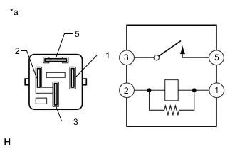
INSPECT PTC HEATER RELAY
-
Measure the resistance according to the value(s) in the table below.
Standard Resistance Tester Connection Condition Specified Condition 3 - 5 Battery voltage is not applied between terminals 1 and 2 10 kΩ or higher 3 - 5 Battery voltage is applied between terminals 1 and 2 Below 1 Ω Result Proceed to OK NG
NG
REPLACE PTC HEATER RELAY Click here
OK
-
-
CHECK HARNESS AND CONNECTOR (PTC HEATER RELAY - POWER SOURCE)
-
Measure the voltage according to the value(s) in the table below.
Standard Voltage PTC HTR NO. 1 Tester Connection Condition Specified Condition Relay terminal 3 - Body ground Always 11 to 14 V Relay terminal 2 - Body ground Engine switch off Below 1 V Relay terminal 2 - Body ground Engine switch on (IG) 11 to 14 V Standard Voltage PTC HTR NO. 2 Tester Connection Condition Specified Condition Relay terminal 3 - Body ground Always 11 to 14 V Relay terminal 2 - Body ground Engine switch off Below 1 V Relay terminal 2 - Body ground Engine switch on (IG) 11 to 14 V Result Proceed to OK NG
NG
REPAIR OR REPLACE HARNESS OR CONNECTOR
OK
-
-
CHECK HARNESS AND CONNECTOR (PTC HEATER RELAY - AIR CONDITIONING AMPLIFIER ASSEMBLY)
-
Disconnect the K10 air conditioning amplifier assembly connector.
-
Measure the resistance according to the value(s) in the table below.
Standard Resistance PTC HTR NO. 1 Tester Connection Condition Specified Condition Relay terminal 1 - K10-8 (PTC1) Always Below 1 Ω Relay terminal 1 - Body ground Always 10 kΩ or higher Standard Resistance PTC HTR NO. 2 Tester Connection Condition Specified Condition Relay terminal 1 - K10-26 (PTC2) Always Below 1 Ω Relay terminal 1 - Body ground Always 10 kΩ or higher Result Proceed to OK NG
NG
REPAIR OR REPLACE HARNESS OR CONNECTOR
OK
-
-
CHECK HARNESS AND CONNECTOR (PTC HEATER RELAY - QUICK HEATER ASSEMBLY AND BODY GROUND)
-
Disconnect the K13 and K14 quick heater assembly connectors.
-
Measure the resistance according to the value(s) in the table below.
Standard Resistance PTC HTR NO. 1 Tester Connection Condition Specified Condition Relay terminal 5 - K13-2 (B) Always Below 1 Ω K13-1 (E) - Body ground Always Below 1 Ω K13-2 (B) - Body ground Always 10 kΩ or higher Standard Resistance PTC HTR NO. 2 Tester Connection Condition Specified Condition Relay terminal 5 - K14-2 (B) Always Below 1 Ω K14-1 (E) - Body ground Always Below 1 Ω K14-2 (B) - Body ground Always 10 kΩ or higher Result Proceed to OK NG
NG
REPAIR OR REPLACE HARNESS OR CONNECTOR
OK
-
-
INSPECT QUICK HEATER ASSEMBLY
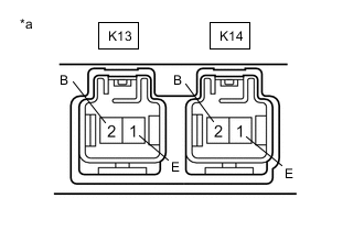
*a Component without harness connected
(Quick Heater Assembly)
-
Remove the quick heater assembly.
-
Measure the resistance according to the value(s) in the table below.
Standard Resistance Tester Connection Condition Specified Condition K13-1 (E) - K13-2 (B) Always Below 1 Ω K14-1 (E) - K14-2 (B) Always Below 1 Ω K13-1 (E) - K14-1 (E) Always 10 kΩ or higher Result Proceed to OK NG
OK
REPLACE AIR CONDITIONING AMPLIFIER ASSEMBLY Click here
NG
REPLACE QUICK HEATER ASSEMBLY Click here
-