VEHICLE STABILITY CONTROL SYSTEM, Diagnostic DTC:C1432

| DTC Code | DTC Name |
|---|---|
| C1432 | Steering Angle Sensor Power Source Voltage Malfunction |
DESCRIPTION
This DTC is stored when the skid control ECU (brake actuator assembly) receives a power supply open signal from the steering angle sensor.
| DTC No. | Detection Item | DTC Detection Condition | Trouble Area |
|---|---|---|---|
| C1432 | Steering Angle Sensor Power Source Voltage Malfunction | Steering angle sensor power supply malfunction signal is received from steering angle sensor. |
|
CAUTION / NOTICE / HINT
Note
Inspect the fuses for circuits related to this system before performing the following procedure.
PROCEDURE
-
CHECK VEHICLE
-
Check the VGRS system.
Result Result Proceed to w/o VGRS system A w/ VGRS system B
B 
CHECK HARNESS AND CONNECTOR (POWER SOURCE TERMINAL) Click here
A 
-
-
CHECK HARNESS AND CONNECTOR (POWER SOURCE TERMINAL)
-
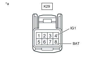
*a Front view of wire harness connector
(to Steering Angle Sensor)
Remove the steering wheel and column cover.
-
Make sure that there is no looseness at the locking part and the connecting part of the connector.
-
Disconnect the K29 steering angle sensor connector.
-
Measure the voltage according to the value(s) in the table below.
Standard Voltage Tester Connection Condition Specified Condition K29-8 (BAT) - Body ground Always 11 to 14 V K29-4 (IG1) - Body ground Engine switch on (IG) 11 to 14 V Result Proceed to OK NG
NG 
REPAIR OR REPLACE HARNESS OR CONNECTOR (POWER SOURCE CIRCUIT)
OK
-
-
CHECK HARNESS AND CONNECTOR (GROUND TERMINAL)
-
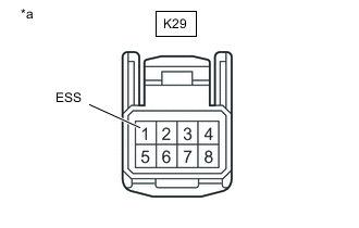
*a Front view of wire harness connector
(to Steering Angle Sensor)
Turn the engine switch off.
-
Measure the resistance according to the value(s) in the table below.
Note
Before measuring the resistance of the steering angle sensor, turn the engine switch off and leave the vehicle for 1 minute or more without operating the key, switches or opening or closing the doors.
Standard Resistance Tester Connection Condition Specified Condition K29-1 (ESS) - Body ground 1 minute after engine switch off Below 1 Ω Result Proceed to OK NG Tech Tips
If troubleshooting has been carried out according to Problem Symptoms Table, refer back to the table and proceed to the next step before replacing parts.
OK
REPLACE STEERING ANGLE SENSOR Click here
NG
REPAIR OR REPLACE HARNESS OR CONNECTOR (GROUND CIRCUIT)
-
-
CHECK HARNESS AND CONNECTOR (POWER SOURCE TERMINAL)
-
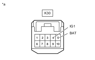
*a Front view of wire harness connector
(to Steering Angle Sensor)
Remove the steering wheel and column cover.
-
Make sure that there is no looseness at the locking part and the connecting part of the connector.
-
Disconnect the K30 steering angle sensor connector.
-
Measure the voltage according to the value(s) in the table below.
Standard Voltage Tester Connection Condition Specified Condition K30-5 (BAT) - Body ground Always 11 to 14 V E30-4 (IG1) - Body ground Engine switch on (IG) 11 to 14 V Result Proceed to OK NG
NG
REPAIR OR REPLACE HARNESS OR CONNECTOR (POWER SOURCE CIRCUIT)
OK
-
-
CHECK HARNESS AND CONNECTOR (GROUND TERMINAL)
-
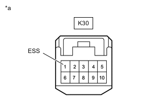
*a Front view of wire harness connector
(to Steering Angle Sensor)
Turn the engine switch off.
-
Measure the resistance according to the value(s) in the table below.
Note
Before measuring the resistance of the steering angle sensor, turn the engine switch off and leave the vehicle for 1 minute or more without operating the key, switches or opening or closing the doors.
Standard Resistance Tester Connection Condition Specified Condition K30-1 (ESS) - Body ground 1 minute after engine switch off Below 1 Ω Result Proceed to OK NG Tech Tips
If troubleshooting has been carried out according to Problem Symptoms Table, refer back to the table and proceed to the next step before replacing parts.
OK
REPLACE STEERING ANGLE SENSOR Click here
NG
REPAIR OR REPLACE HARNESS OR CONNECTOR (GROUND CIRCUIT)
-