VEHICLE STABILITY CONTROL SYSTEM, Diagnostic DTC:C120B

| DTC Code | DTC Name |
|---|---|
| C120B | IG Supply Voltage Low |
DESCRIPTION
| DTC No. | Detection Item | DTC Detection Condition | Trouble Area |
|---|---|---|---|
| C120B | IG Supply Voltage Low | Either of the following is detected:
|
|
CAUTION / NOTICE / HINT
Note
-
When replacing the skid control ECU (brake actuator assembly), perform zero point calibration and store system information.
-
Inspect the fuses for circuits related to this system before performing the following procedure.
PROCEDURE
-
CHECK HARNESS AND CONNECTOR (IG1 TERMINAL)
-
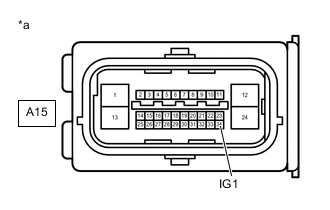
*a Front view of wire harness connector
(to Skid Control ECU (Brake Actuator Assembly))
Make sure that there is no looseness at the locking part and the connecting part of the connector.
-
Disconnect the A15 skid control ECU (brake actuator assembly) connector.
-
Turn the engine switch on (IG).
-
Measure the voltage according to the value(s) in the table below.
Standard Voltage Tester Connection Condition Specified Condition A15-34 (IG1) - Body ground Engine switch on (IG) 11 to 14 V Result Proceed to OK NG
NG 
REPAIR OR REPLACE HARNESS OR CONNECTOR (IG1 CIRCUIT)
OK 
-
-
RECONFIRM DTC
-
Reconnect the A15 skid control ECU (brake actuator assembly) connector.
-
Clear the DTCs.
Chassis > ABS/VSC/TRC > Clear DTCs -
Check if the same DTC is output.
Chassis > ABS/VSC/TRC > Trouble CodesResult Result Proceed to DTC C120B is not output. A DTC C120B is output. B
A
USE SIMULATION METHOD TO CHECK Click here
B
REPLACE BRAKE ACTUATOR ASSEMBLY for LHD: Click here
REPLACE BRAKE ACTUATOR ASSEMBLY for RHD: Click here -