REAR DIFFERENTIAL CARRIER ASSEMBLY(for 4GR-FSE) REASSEMBLY

PROCEDURE
-
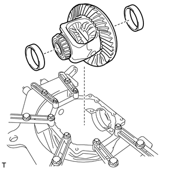
INSTALL DIFFERENTIAL RING GEAR
-
Clean the contact surfaces of the rear differential case sub-assembly and differential ring gear.
-
Clean the rear differential ring gear set bolt hole.
-
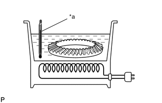
*a 100°C (212°F) Heat the differential ring gear to approximately 100°C (212°F) in boiling water.
-
Carefully take the differential ring gear out of the boiling water.
CAUTION:
Use thick gloves to protect your hands as the differential ring gear is hot.
-
Secure the rear differential case sub-assembly between aluminum plates in a vise.
Note
Do not overtighten the vise.
-
*a Matchmark After the moisture on the differential ring gear has completely evaporated, quickly install the differential ring gear to the rear differential case sub-assembly.
-
Align the matchmarks on the differential ring gear and rear differential case sub-assembly.
-
Temporarily install 5 new rear differential ring gear set bolt lock plates with the 10 bolts.
-
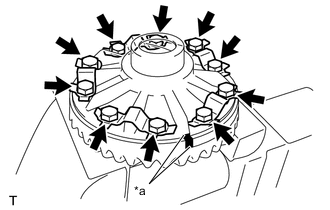
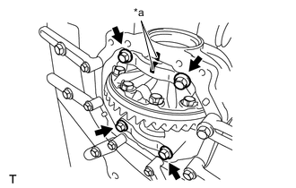
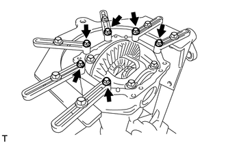
After the differential ring gear cools down, tighten the 10 bolts uniformly.
- Torque:
- 96.5 N*m { 984 kgf*cm, 71 ft.*lbf }
Note
Tighten diametrically opposite ring gear set bolts in pairs.
-
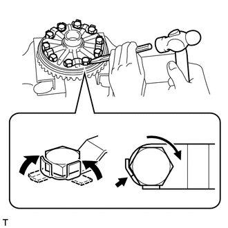
Using a chisel and hammer, stake the 5 rear differential ring gear set bolt lock plates.
-
Stake one claw so that it is flush against the flat surface of the bolt.
-
Stake the other claw against the surface of the bolt head to act as a stopper if the bolt starts to loosen.
-
-
-
INSTALL REAR DIFFERENTIAL CASE BEARING
-
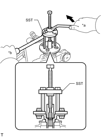
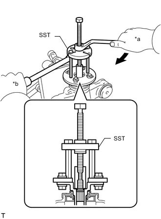
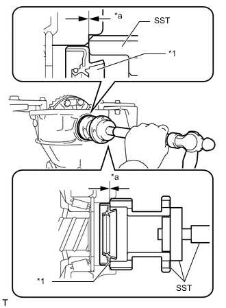
Using SST and a press, install the rear differential case bearing inner races LH and RH to the rear differential case sub-assembly.
- SST
- 09710-30012 ( 09710-04081 )
- 09950-60010 ( 09951-00430, 09951-00580, 09951-00590, 09952-06010 )
- 09950-70010 ( 09951-07100 )
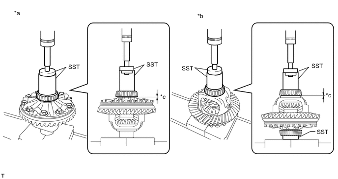
*a for LH Side *b for RH Side *c 0 mm (0 in.) - - Note
-
Do not apply hypoid gear oil to a new bearing.
-
Set SST to the center of the rear differential case sub-assembly.
-
If the bearing is replaced, replace it and its outer race as a set.
-
Do not deform the bearing cage.
-
-
INSPECT RUNOUT OF DIFFERENTIAL RING GEAR
-
Install the rear differential case bearing outer races LH and RH to the rear differential case bearing inner races LH and RH respectively.
Note
Be sure to install the rear differential case bearing outer races in the correct position.
Note
-
Be sure to install the rear differential case bearing outer races in the correct position.
-
Do not apply hypoid gear oil to a new bearing.
-
-
Install the rear differential case sub-assembly to the rear differential carrier.
-
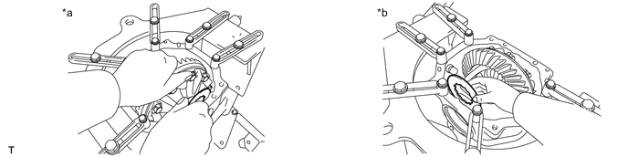
Install the right and left (back side and teeth side) rear differential side gear shaft plate washers so that there is no looseness in the case bearings.

*a Left (Differential Ring Gear Back) Side *b Right (Differential Ring Gear Teeth) Side Tech Tips
-
If the rear differential case bearing is new, select a thinner rear differential side gear shaft plate washer and install it.
-
If the rear differential case bearing is reused, install a rear differential side gear shaft plate washer with the same thickness as the removed one.
-
-
*a Matchmark Align the matchmarks on the bearing cap and rear differential carrier and install the 2 bearing caps.
Note
Make sure that the right and left bearing caps are not interchanged.
-
Tighten both bearing caps with the 4 bolts.
- Torque:
- 85.3 N*m { 870 kgf*cm, 63 ft.*lbf }
-
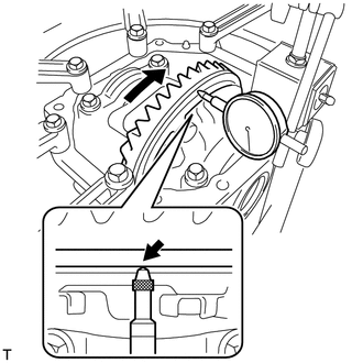
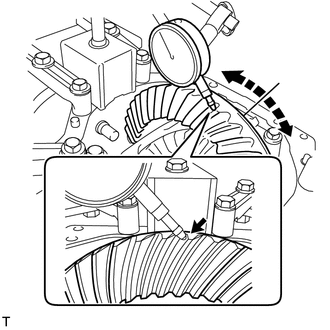
Using a dial indicator, measure the runout of the differential ring gear.
Maximum runout 0.07 mm (0.00275 in.) -
*a Matchmark Remove the 4 bolts and 2 bearing caps.
Note
Do not exchange bearing caps, as each cap is only suitable for its original location and the installation direction relative to the carrier for which it was manufactured.
-
Remove the right and left (back side and teeth side) rear differential side gear shaft plate washers.
*a Left (Differential Ring Gear Back) Side *b Right (Differential Ring Gear Teeth) Side -
Remove the right and leftrear rear differential case bearing and rear differential case sub-assembly.
Note
Do not damage the rear differential case bearing or differential ring gear.
-
-
INSTALL REAR DRIVE PINION REAR TAPERED ROLLER BEARING
-
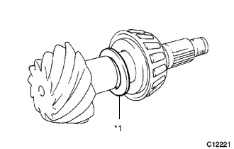
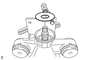
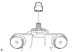
*1 Rear Differential Drive Pinion Plate Washer Install the rear differential drive pinion plate washer to the differential drive pinion.
Tech Tips
-
Temporarily install the inner race of the rear drive pinion rear tapered roller bearing to prevent the rear differential drive pinion plate washer from being dropped.
-
The rear differential drive pinion plate washer can be installed in either direction.
-
-
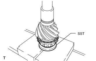
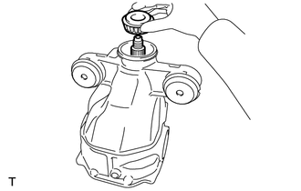
Using SST and a press, install the inner race of the rear drive pinion rear tapered roller bearing to the differential drive pinion.
- SST
- 09506-30012
Note
Do not apply hypoid gear oil to a new bearing.
-
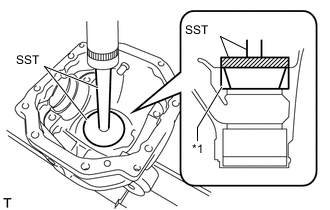
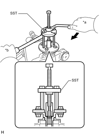
*1 Rear Drive Pinion Rear Tapered Roller Bearing Outer Race Using SST and a press, install the rear drive pinion rear tapered roller bearing outer race to the rear differential carrier.
- SST
- 09950-60020 ( 09951-00890 )
- 09950-70010 ( 09951-07200 )
Note
Do not apply hypoid gear oil to a new bearing.
-
-
INSTALL REAR DRIVE PINION FRONT TAPERED ROLLER BEARING
-
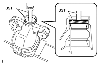
*1 Rear Drive Pinion Front Tapered Roller Bearing Outer Race Using SST and a press, install the rear drive pinion front tapered roller bearing outer race to the rear differential carrier.
- SST
- 09950-60020 ( 09951-00720 )
- 09950-70010 ( 09951-07100 )
Note
Do not apply hypoid gear oil to a new bearing.
-
-
INSTALL REAR DIFFERENTIAL DUST DEFLECTOR
Tech Tips
Perform this procedure only when replacing the rear differential dust deflector.
-
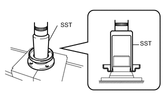
Using SST and a press, install a new rear differential dust deflector to the rear drive pinion companion flange.
- SST
- 09636-20010
Note
-
Slowly press in the rear differential dust deflector.
-
If any burrs remain after pressing in the rear differential dust deflector, remove them.
-
-
INSTALL REAR DRIVE PINION COMPANION FLANGE
-
Install the differential drive pinion and rear drive pinion front tapered roller bearing inner race to the rear differential carrier.
Note
-
Do not drop the differential drive pinion.
-
Install the rear differential drive pinion bearing spacer and rear differential carrier oil seal after adjusting the tooth contact pattern.
-
Do not apply hypoid gear oil to a new bearing.
-
-
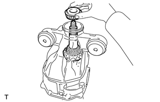
Install the rear differential drive pinion oil slinger to the differential drive pinion.
-
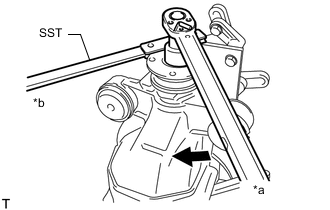
*a Turn *b Hold Using SST, install the rear drive pinion companion flange.
- SST
- 09950-30012 ( 09951-03010, 09953-03010, 09954-03010, 09955-03030, 09956-03030 )
Note
-
Hold the differential drive pinion until SST is installed.
-
Install the rear drive pinion companion flange so that there is a slight looseness in the differential drive pinion because the rear differential drive pinion bearing spacer is not yet installed.
-
Apply molybdenum grease to the threads and tip of SST center bolt (09953-03010) before use.
Tech Tips
When securing SST and the companion flange, it is recommended to use M8 X P 1.25 bolts with a length of approximately 40 mm.
-
Coat the threads of a new rear drive pinion nut with hypoid gear oil LSD.
-
*a Turn *b Hold Using SST and a torque wrench, hold the rear drive pinion companion flange and temporary tighten the rear drive pinion nut.
- SST
- 09330-00021
- Torque:
- 100 N*m { 1020 kgf*cm, 74 ft.*lbf }
CAUTION:
Hold the overhaul attachment during the operation.
Note
Apply hypoid gear oil LSD to the rear drive pinion nut and the threads of the differential drive pinion.
Tech Tips
Tighten the nut approximately 100 N*m (1020 kgf*cm, 74 ft.*lbf), and tighten it further while checking the preload.
-
-
ADJUST DIFFERENTIAL DRIVE PINION PRELOAD
-
Turn the bearing clockwise and counterclockwise several times to stabilize it.
-
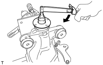
Using a torque wrench, measure the starting torque of the differential drive pinion.
Differential Drive Pinion Preload (at Starting) Item Specified Condition New rear drive pinion tapered roller bearing 1.77 to 2.14 N*m (18.0 to 21.8 kgf*cm, 15.7 to 18.9 in.*lbf) Reused rear drive pinion tapered roller bearing 1.77 to 2.07 N*m (18.0 to 21.1 kgf*cm, 15.7 to 18.3 in.*lbf)
-
If the preload is less than the specified minimum value, check the preload while retightening the drive pinion nut by 5 to 10° to adjust it into the specified range.
Torque 337.8 N*m (3445 kgf*cm, 249 ft.*lbf) or less
Note
As there is no rear differential drive pinion bearing spacer, tighten the rear drive pinion nut a little at a time. Do not overtighten it.
Tech Tips
The backlash between the differential drive pinion and differential ring gear should allow enough movement of the differential drive pinion to allow this measurement to be performed.
-
-
-
INSTALL REAR DIFFERENTIAL CASE SUB-ASSEMBLY
-
Install the rear differential case bearing outer races LH and RH to the rear differential case bearing inner races LH and RH respectively.
Note
Be sure to install the rear differential case bearing outer races in the correct position.
-
Install the rear differential case sub-assembly to the rear differential carrier.
-
Install the right and left (back and teeth side) rear differential side gear shaft plate washers so that the rear differential case bearing is not loose.
*a Left (Differential Ring Gear Back) Side *b Right (Differential Ring Gear Teeth) Side Tech Tips
-
If the final gear set (differential drive pinion and differential ring gear) and rear differential case bearing are new, select a thinner rear differential side gear shaft plate washer and install it.
-
If the final gear set (differential drive pinion and differential ring gear) and rear differential case bearing are reused, install a rear differential side gear shaft plate washer with the same thickness as the removed one.
-
-
-
INSPECT AND ADJUST DIFFERENTIAL RING GEAR BACKLASH
-
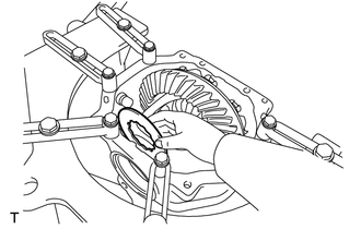
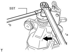
While holding the rear drive pinion companion flange, rotate the differential ring gear and measure the backlash.
Backlash 0.13 to 0.18 mm (0.00512 to 0.00708 in.) Tech Tips
-
Record the measured backlash to use as a reference for selecting a rear differential side gear shaft plate washer.
-
Inspect the tooth contact and use the result as a reference for selecting a rear differential side gear shaft plate washer.
-
-
Select a new rear differential side gear shaft plate washer so that the differential ring gear backlash will be within the specified range, and install it to the differential ring gear back side.
Rear Differential Side Gear Shaft Plate Washer Thickness Part No. No. Thickness Part No. No. Thickness 90201-52001 01 2.57 to 2.59 mm (0.1012 to 0.1020 in.) 90564-46029 47 3.03 to 3.05 mm (0.1193 to 0.1201 in.) 90564-46014 32 2.59 to 2.61 mm (0.1020 to 0.1028 in.) 90201-52017 17 3.05 to 3.07 mm (0.1201 to 0.1209 in.) 90564-46015 33 2.61 to 2.63 mm (0.1028 to 0.1035 in.) 90564-46030 48 3.07 to 3.09 mm (0.1209 to 0.1217 in.) 90201-52003 03 2.63 to 2.65 mm (0.1035 to 0.1043 in.) 90564-46031 49 3.09 to 3.11 mm (0.1217 to 0.1224 in.) 90564-46016 34 2.65 to 2.67 mm (0.1043 to 0.1051 in.) 90201-52019 19 3.11 to 3.13 mm (0.1224 to 0.1232 in.) 90564-46017 35 2.67 to 2.69 mm (0.1051 to 0.1059 in.) 90564-46032 50 3.13 to 3.15 mm (0.1232 to 0.1240 in.) 90201-52005 05 2.69 to 2.71 mm (0.1059 to 0.1067 in.) 90564-46033 51 3.15 to 3.17 mm (0.1240 to 0.1248 in.) 90564-46018 36 2.71 to 2.73 mm (0.1067 to 0.1075 in.) 90201-52021 21 3.17 to 3.19 mm (0.1248 to 0.1256 in.) 90564-46019 37 2.73 to 2.75 mm (0.1075 to 0.1083 in.) 90564-46034 52 3.19 to 3.21 mm (0.1256 to 0.1264 in.) 90201-52007 07 2.75 to 2.77 mm (0.1083 to 0.1091 in.) 90564-46035 53 3.21 to 3.23 mm (0.1264 to 0.1271 in.) 90564-46020 38 2.77 to 2.79 mm (0.1091 to 0.1098 in.) 90201-52023 23 3.23 to 3.25 mm (0.1271 to 0.1280 in.) 90564-46021 39 2.79 to 2.81 mm (0.1098 to 0.1106 in.) 90564-46036 54 3.25 to 3.27 mm (0.1280 to 0.1287 in.) 90201-52009 09 2.81 to 2.83 mm (0.1106 to 0.1114 in.) 90564-46037 55 3.27 to 3.29 mm (0.1287 to 0.1295 in.) 90564-46022 40 2.83 to 2.85 mm (0.1114 to 0.1122 in.) 90201-52025 25 3.29 to 3.31 mm (0.1295 to 0.1303 in.) 90564-46023 41 2.85 to 2.87 mm (0.1122 to 0.1130 in.) 90564-46038 56 3.31 to 3.33 mm (0.1303 to 0.1311 in.) 90201-52011 11 2.87 to 2.89 mm (0.1130 to 0.1138 in.) 90564-46039 57 3.33 to 3.35 mm (0.1311 to 0.1319 in.) 90564-46024 42 2.89 to 2.91 mm (0.1138 to 0.1146 in.) 90201-52027 27 3.35 to 3.37 mm (0.1319 to 0.1327 in.) 90564-46025 43 2.91 to 2.93 mm (0.1146 to 0.1154 in.) 90564-46040 58 3.37 to 3.39 mm (0.1327 to 0.1335 in.) 90201-52013 13 2.93 to 2.95 mm (0.1154 to 0.1161 in.) 90564-46041 59 3.39 to 3.41 mm (0.1335 to 0.1343 in.) 90564-46026 44 2.95 to 2.97 mm (0.1161 to 0.1169 in.) 90201-52029 29 3.41 to 3.43 mm (0.1343 to 0.1350 in.) 90564-46027 45 2.97 to 2.99 mm (0.1169 to 0.1177 in.) 90564-46042 60 3.43 to 3.45 mm (0.1350 to 0.1358 in.) 90201-52015 15 2.99 to 3.01 mm (0.1177 to 0.1185 in.) 90564-46043 61 3.45 to 3.47 mm (0.1358 to 0.1366 in.) 90564-46028 46 3.01 to 3.03 mm (0.1185 to 0.1193 in.) 90201-52031 31 3.47 to 3.49 mm (0.1366 to 0.1374 in.) -
Make the rear differential case bearing and rear differential side gear shaft plate washer snug by tapping on the rear differential carrier with a plastic-faced hammer.
-
Set a dial indicator perpendicular to the end of the differential ring gear face.
-
While holding the rear drive pinion companion flange, rotate the differential ring gear and measure the backlash.
Standard Backlash 0.13 to 0.18 mm (0.00512 to 0.00708 in.) -
If the backlash is not within the specified range, select a new rear differential side gear shaft plate washer so that the differential ring gear backlash will be within the specified range, and install it to the differential ring gear back side.
-
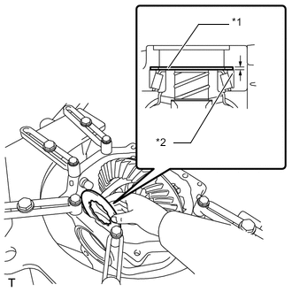
*1 Rear Differential Side Gear Shaft Plate Washer *2 Rear Differential Case Bearing Outer Race Select a thicker rear differential side gear shaft plate washer so that the clearance becomes zero or close to zero.
-
Make the rear differential case bearing and rear differential side gear shaft plate washer snug by tapping on the rear differential carrier with a plastic-faced hammer.
-
Set a dial indicator perpendicular to the end of the differential ring gear face.
-
While holding the rear drive pinion companion flange, rotate the differential ring gear and measure the backlash.
Standard Backlash 0.13 to 0.18 mm (0.00512 to 0.00708 in.) If the backlash is not within the specified range, adjust the thickness of the right and left rear differential side gear shaft plate washers by an equal amount so that the backlash is within the specified range.
-
-
ADJUST REAR DIFFERENTIAL CASE BEARING PRELOAD
-
After adjusting the backlash of the differential ring gear, remove the teeth side rear differential side gear shaft plate washer.
-
Using a micrometer, measure the thickness of the removed rear differential side gear shaft plate washer.
-
Select a new rear differential side gear shaft plate washer which is 0.06 to 0.09 mm (0.00236 to 0.00354 in.) thicker than the removed one.
Note
Select a rear differential side gear shaft plate washer which can be pressed in 2/3 of the way with a finger.
-
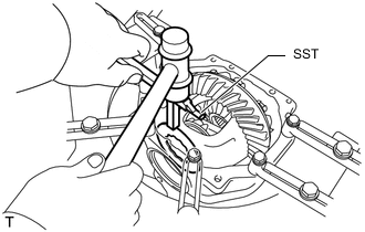
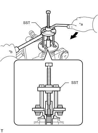
Using SST and a plastic-faced hammer, drive in the rear differential side gear shaft plate washer.
- SST
- 09504-22011
-
*a Matchmark Align the matchmarks on the bearing cap and rear differential carrier and install the 2 bearing caps.
Note
Make sure that the right and left bearing caps are not interchanged.
-
Tighten both bearing caps with the 4 bolts.
- Torque:
- 85.3 N*m { 870 kgf*cm, 63 ft.*lbf }
-
Set a dial indicator to the end of the differential ring gear face.
-
While holding the rear drive pinion companion flange, rotate the differential ring gear and measure the backlash.
Standard Backlash 0.13 to 0.18 mm (0.00512 to 0.00708 in.) If the measured value is out of the specified range, adjust it by increasing or decreasing the thickness of both the right and left rear differential side gear shaft plate washers equally.
Tech Tips
-
Record the measured backlash to use as a reference for selecting a rear differential side gear shaft plate washer.
-
Inspect the tooth contact and use the result as a reference for selecting a rear differential side gear shaft plate washer.
-
-
-
INSPECT TOTAL PRELOAD
-
Using a torque wrench, measure the preload with the teeth of the differential drive pinion and differential ring gear in contact.
Total Preload (at Starting) Identification Mark Item New rear drive pinion tapered roller bearing Reused rear drive pinion tapered roller bearing 3.7 New differential case bearing 2.17 to 2.84 N*m (22.1 to 29.0 kgf*cm, 19.2 to 25.1 in.*lbf) 2.17 to 2.77 N*m (22.1 to 28.4 kgf*cm, 19.2 to 24.5 in.*lbf) Reused differential case bearing 2.09 to 2.73 N*m (21.3 to 27.8 kgf*cm, 18.5 to 24.2 in.*lbf) 2.09 to 2.66 N*m (21.3 to 27.1 kgf*cm, 18.5 to 23.5 in.*lbf) 3.9 New differential case bearing 2.16 to 2.81 N*m (22.0 to 28.7 kgf*cm, 19.1 to 24.9 in.*lbf) 2.16 to 2.74 N*m (22.0 to 27.9 kgf*cm, 19.1 to 24.2 in.*lbf) Reused differential case bearing 2.07 to 2.70 N*m (21.1 to 27.5 kgf*cm, 18.3 to 23.9 in.*lbf) 2.07 to 2.63 N*m (21.1 to 26.8 kgf*cm, 18.3 to 23.3 in.*lbf) If the measured preload is less than the specified value, replace the rear differential side gear shaft plate washer of the differential ring gear tooth surface side with a new thicker one.If the preload is more than the specified value, replace the rear differential side gear shaft plate washer of the differential ring gear tooth surface side with a new thinner one.
Note
Make sure to check the identification mark because total preload is different between the 2 types of ring gears.
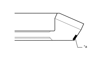
*a Identification Mark Position -
Set a dial indicator perpendicular to the end of the differential ring gear face.
-
While holding the rear drive pinion companion flange, rotate the differential ring gear and measure the backlash.
Standard Backlash 0.13 to 0.18 mm (0.00512 to 0.00708 in.) If the backlash is not within the specified range, change the thickness of the right and left rear differential side gear shaft plate washers by equal amounts to adjust it.
Tech Tips
-
Record the measured backlash to use as a reference for selecting a rear differential side gear shaft plate washer.
-
Inspect the tooth contact and use the result as a reference for selecting a rear differential side gear shaft plate washer.
-
-
-
INSPECT TOOTH CONTACT BETWEEN RING GEAR AND DRIVE PINION
-
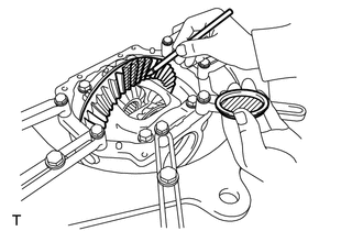
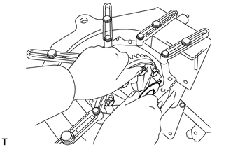
Coat 3 or 4 teeth at 3 different positions on the differential ring gear with Prussian blue.
-
Rotate the differential ring gear in both directions.
-
Inspect the tooth contact pattern.
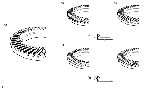
*a Proper Contact *b Heel Contact *c Face Contact *d Select an adjusting washer that will shift the drive pinion closer to the ring gear (*b, *c) *e Toe Contact *f Flank Contact *g Select an adjusting washer that will shift the drive pinion away from the ring gear (*e, *f) - - Note
Check the tooth contact pattern at 4 or more positions around circumference of the differential ring gear.
-
*1 Rear Differential Drive Pinion Plate Washer If the teeth are not contacting properly, use the following table to select a proper rear differential drive pinion plate washer for correction.
Note
-
If the contact pattern is face contact or flank contact, tooth contact may be adjustable while keeping the backlash within the specified range.
-
If the thickness of the rear differential drive pinion plate washer has been changed, adjust the backlash and measure the total preload.
Rear Differential Drive Pinion Plate Washer Thickness Part No. Thickness Part No. Thickness 90201-35497 1.69 to 1.71 mm (0.0665 to 0.0673 in.) 90201-35508 2.02 to 2.04 mm (0.0795 to 0.0803 in.) 90201-35498 1.72 to 1.74 mm (0.0677 to 0.0685 in.) 90201-35509 2.05 to 2.07 mm (0.0807 to 0.0815 in.) 90201-35499 1.75 to 1.77 mm (0.0688 to 0.0697 in.) 90201-35510 2.08 to 2.10 mm (0.0819 to 0.0827 in.) 90201-35500 1.78 to 1.80 mm (0.0701 to 0.0709 in.) 90201-35511 2.11 to 2.13 mm (0.0831 to 0.0839 in.) 90201-35501 1.81 to 1.83 mm (0.0713 to 0.0720 in.) 90201-35512 2.14 to 2.16 mm (0.0843 to 0.0850 in.) 90201-35502 1.84 to 1.86 mm (0.0724 to 0.0732 in.) 90201-35513 2.17 to 2.19 mm (0.0854 to 0.0862 in.) 90201-35503 1.87 to 1.89 mm (0.0736 to 0.0744 in.) 90201-35514 2.20 to 2.22 mm (0.0866 to 0.0874 in.) 90201-35504 1.90 to 1.92 mm (0.0748 to 0.0756 in.) 90201-35515 2.23 to 2.25 mm (0.0878 to 0.0886 in.) 90201-35505 1.93 to 1.95 mm (0.0760 to 0.0768 in.) 90201-35516 2.26 to 2.28 mm (0.0890 to 0.0898 in.) 90201-35506 1.96 to 1.98 mm (0.0772 to 0.0780 in.) 90201-35517 2.29 to 2.31 mm (0.0902 to 0.0909 in.) 90201-35507 1.99 to 2.01 mm (0.0783 to 0.0791 in.) 90201-35518 2.32 to 2.34 mm (0.0913 to 0.0921 in.) -
-
-
REMOVE REAR DRIVE PINION NUT
-
*a Turn *b Hold Using SST to hold the rear drive pinion companion flange, remove the rear drive pinion nut.
- SST
- 09330-00021
CAUTION:
Hold the overhaul attachment during the operation.
-
-
REMOVE REAR DRIVE PINION COMPANION FLANGE
-
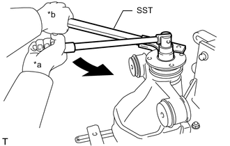
*a Turn *b Hold Using SST, remove the rear drive pinion companion flange.
- SST
- 09950-30012 ( 09951-03010, 09953-03010, 09954-03010, 09955-03030, 09956-03030 )
Note
Apply molybdenum grease to the threads of SST center bolt (09953-03010) before use.
Tech Tips
When securing SST and the companion flange, it is recommended to use M8 X P 1.25 bolts with a length of approximately 45 mm.
-
-
REMOVE REAR DIFFERENTIAL DRIVE PINION OIL SLINGER
-
REMOVE REAR DRIVE PINION FRONT TAPERED ROLLER BEARING
-
INSTALL REAR DIFFERENTIAL DRIVE PINION BEARING SPACER
-
Install a new rear differential drive pinion bearing spacer to the differential drive pinion.
Note
Be sure to install the spacer so that the side with the larger inner diameter faces the rear differential carrier as shown in the illustration.
-
-
INSTALL REAR DRIVE PINION FRONT TAPERED ROLLER BEARING
-
Install the rear drive pinion front tapered roller bearing to the differential drive pinion.
-
-
INSTALL REAR DIFFERENTIAL DRIVE PINION OIL SLINGER
-
Install the rear differential drive pinion oil slinger to the differential drive pinion.
-
-
INSTALL REAR DRIVE PINION COMPANION FLANGE
-
*a Turn *b Hold Using SST and a rear drive pinion companion flange, install the rear drive pinion companion flange and rear drive pinion front tapered roller bearing.
- SST
- 09950-30012 ( 09951-03010, 09953-03010, 09954-03010, 09955-03030, 09956-03030 )
Note
Apply molybdenum grease to the threads of SST center bolt (09953-03010) before use.
Tech Tips
When securing SST and the companion flange, it is recommended to use M8 X P 1.25 bolts with a length of approximately 45 mm.
-
-
REMOVE REAR DRIVE PINION COMPANION FLANGE
-
*a Turn *b Hold Using SST, remove the rear drive pinion companion flange.
- SST
- 09950-30012 ( 09951-03010, 09953-03010, 09954-03010, 09955-03030 )
Note
Apply molybdenum grease to the threads of SST center bolt (09953-03010) before use.
Tech Tips
When securing SST and the companion flange, it is recommended to use M8 X P 1.25 bolts with a length of approximately 45 mm.
-
-
INSTALL REAR DIFFERENTIAL CARRIER OIL SEAL
-
INSTALL REAR DRIVE PINION COMPANION FLANGE
-
*a Turn *b Hold Using SST, install the rear drive pinion companion flange.
- SST
- 09950-30012 ( 09951-03010, 09953-03010, 09954-03010, 09955-03030, 09956-03030 )
Note
Apply molybdenum grease to the threads of SST center bolt (09953-03010) before use.
Tech Tips
When securing SST and the companion flange, it is recommended to use M8 X P 1.25 bolts with a length of approximately 45 mm.
-
Coat the threads of the rear drive pinion nut with hypoid gear oil LSD.
-
*a Turn *b Hold Using SST and a torque wrench, hold the rear drive pinion companion flange and temporary tighten the rear drive pinion nut.
- SST
- 09330-00021
- Torque:
- 100 N*m { 1020 kgf*cm, 74 ft.*lbf }
CAUTION:
Hold the overhaul attachment during the operation.
Note
-
Do not tighten the nut excessively, otherwise the threads will be stripped.
-
Apply hypoid gear oil LSD to the threads of the drive pinion nut and differential drive pinion.
Tech Tips
Tighten the drive pinion nut to approximately 100 N*m (1020 kgf*cm, 74 ft.*lbf), and then tighten it further while observing the preload.
-
-
ADJUST DIFFERENTIAL DRIVE PINION PRELOAD
-
Using a torque wrench, measure the starting torque of the differential drive pinion.
Differential Drive Pinion Preload (at Starting) Item Specified Condition New rear drive pinion tapered roller bearing 1.87 to 2.24 N*m (19.1 to 22.8 kgf*cm, 16.6 to 19.8 in.*lbf) Reused rear drive pinion tapered roller bearing 1.87 to 2.17 N*m (19.1 to 22.1 kgf*cm, 16.6 to 19.2 in.*lbf)
-
If the preload is less than the specified minimum value, check the preload while retightening the drive pinion nut by 5 to 10° to adjust it into the specified range.
Torque 337.8 N*m (3445 kgf*cm, 249 ft.*lbf) or less -
If the preload is less than the specified minimum value, check the preload while retightening the rear drive pinion nut by 5 to 10° to adjust it so that it is within the specified range.
-
If the preload is less than the specified minimum value even when the tightening torque of the rear drive pinion nut is more than the specified maximum value, loosen the rear drive pinion nut and check that the threads of the rear drive pinion nut and differential drive pinion are not stripped.
-
If the threads are not stripped, replace the rear differential drive pinion bearing spacer. Apply hypoid gear oil LSD to the threads of the differential drive pinion and repeat the procedure.
Tech Tips
-
The backlash between the differential drive pinion and differential ring gear should allow enough movement of the differential drive pinion to allow this measurement to be performed.
-
Make sure not to include the preload of the differential ring gear (rear differential case sub-assembly) in the measurement of the differential drive pinion preload.
-
-
-
INSPECT TOTAL PRELOAD
-
Using a torque wrench, measure the preload with the teeth of the drive pinion and ring gear in contact.
Total Preload (at Starting) Identification Mark Item New rear drive pinion tapered roller bearing Reused rear drive pinion tapered roller bearing 3.7 New differential case bearing 2.27 to 2.94 N*m (23.1 to 30.0 kgf*cm, 20.1 to 26.0 in.*lbf) 2.27 to 2.87 N*m (23.1 to 29.3 kgf*cm, 20.1 to 25.4 in.*lbf) Reused differential case bearing 2.19 to 2.83 N*m (22.3 to 28.9 kgf*cm, 19.4 to 25.0 in.*lbf) 2.19 to 2.76 N*m (22.3 to 28.1 kgf*cm, 19.4 to 24.4 in.*lbf) 3.9 New differential case bearing 2.26 to 2.91 N*m (23.0 to 29.7 kgf*cm, 20.0 to 25.8 in.*lbf) 2.26 to 2.84 N*m (23.0 to 29.0 kgf*cm, 20.0 to 25.1 in.*lbf) Reused differential case bearing 2.17 to 2.80 N*m (22.1 to 28.6 kgf*cm, 19.2 to 24.8 in.*lbf) 2.17 to 2.73 N*m (22.1 to 27.8 kgf*cm, 19.2 to 24.2 in.*lbf) If the total preload is not within the specified range, adjust the total preload or perform repairs as necessary.
Note
Make sure to check the identification mark because total preload is different between the 2 types of ring gears.
*a Identification Mark Position
-
-
INSPECT DIFFERENTIAL RING GEAR BACKLASH
-
While holding the rear drive pinion companion flange, rotate the differential ring gear and measure the backlash.
Standard Backlash 0.13 to 0.18 mm (0.00512 to 0.00708 in.) If the backlash is not within the specified range, adjust the backlash or perform repairs as necessary.
-
-
INSPECT RUNOUT OF REAR DRIVE PINION COMPANION FLANGE
-
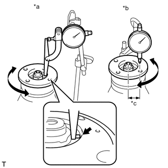
*a Vertical Runout *b Lateral Runout *c 30 mm (1.18 in.) Using a dial indicator, measure the runout of the rear drive pinion companion flange vertically and horizontally.
Maximum Runout Item Specified Condition Vertical runout 0.09 mm (0.00354 in.) Lateral runout 0.09 mm (0.00354 in.) Note
Measure the runout of the rear drive pinion companion flange horizontally at a position 30 mm (1.18 in.) away from the center of the differential drive pinion shaft.
If the runout is more than the maximum value, replace the rear drive pinion companion flange.
-
-
STAKE REAR DRIVE PINION NUT
-
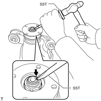
Using SST and a hammer, stake the rear drive pinion nut.
- SST
- 09930-00010
-
-
INSTALL REAR DIFFERENTIAL SIDE GEAR SHAFT OIL SEAL
-
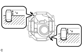
*1 Rear Differential Side Gear Shaft Oil Seal *a Oil Seal Installation Depth Using SST and a hammer, install 2 new rear differential side gear shaft oil seals.
- SST
- 09213-70011
- 09950-60010 ( 09951-00410, 09951-00620, 09952-06010 )
- 09950-70010 ( 09951-07100 )
Oil seal installation depth -0.5 to 0.5 mm (-0.0197 to 0.0197 in.) Note
-
To ensure a proper seal, evenly tap in the rear differential side gear shaft oil seal.
-
When installing the oil seal, tap it in until its surface is flush with the rear differential carrier.
-
Make sure the difference between the maximum and minimum measured values is less than 0.6 mm (0.0236 in.), as a greater difference may lead to oil leaks.
-
-
INSTALL REAR DIFFERENTIAL DRAIN PLUG
-
Using a hexagon wrench, install the rear differential drain plug together with a new gasket.
- Torque:
- 49 N*m { 500 kgf*cm, 36 ft.*lbf }
-
-
REMOVE REAR DIFFERENTIAL CARRIER
-
Remove the rear differential carrier from the overhaul stand.
-
-
INSTALL REAR DIFFERENTIAL BREATHER PLUG OIL DEFLECTOR
-
Clean the seal packing attached to the rear differential carrier and rear differential carrier cover using a scraper and wire brush. Then remove the oil with non-residue solvent or equivalent.
Note
Do not scratch the sealing surface.
-
Install the rear differential breather plug oil deflector to the rear differential carrier cover with the bolt.
- Torque:
- 7.0 N*m { 71 kgf*cm, 62 in.*lbf }
-
-
INSTALL REAR DIFFERENTIAL CARRIER STRAIGHT PIN
Tech Tips
It is not necessary to remove a rear differential carrier straight pin unless it is being replaced.
-
*a Protrusion Using a plastic-faced hammer, install the 2 rear differential carrier straight pins to the rear differential carrier.
Protrusion 8 to 9 mm (0.315 to 0.354 in.)
-
-
INSTALL REAR DIFFERENTIAL CARRIER COVER
-
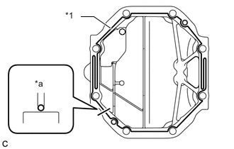
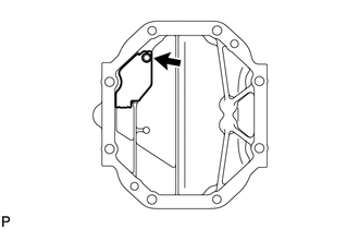
*1 Seal Packing 1281 *a 2 to 3 mm (0.0787 to 0.118 in.) Apply seal packing 1281 to the rear differential carrier as shown in the illustration.
Seal packing Toyota Genuine Seal Packing 1281, Three bond 1281 or equivalent Note
-
Apply the seal packing in a continuous line, approximately 2 to 3 mm (0.0787 to 0.118 in.) in diameter.
-
Overlap the seal packing at least 10 mm (0.394 in.) at the beginning and end of application.
-
Install the rear differential carrier cover within 3 minutes of application.
-
-
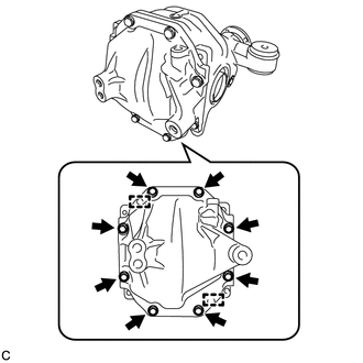
Install the rear differential carrier cover with the 8 bolts.
- Torque:
- 46.6 N*m { 475 kgf*cm, 34 ft.*lbf }
Note
Do not fill the differential with oil or drive the vehicle immediately after installing the differential carrier cover. Leave the vehicle for at least 1 hour. Also, avoid sudden acceleration and deceleration for at least 12 hours after application.
-
-
INSTALL REAR DIFFERENTIAL BREATHER PLUG
-
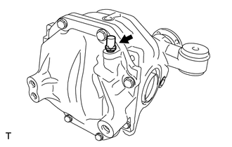
Install the rear differential breather plug to the rear differential carrier cover.
- Torque:
- 20.6 N*m { 210 kgf*cm, 15 ft.*lbf }
-