BRAKE BOOSTER(for RHD) INSTALLATION
PROCEDURE
-
INSTALL VACUUM SENSOR ASSEMBLY (for 8AR-FTS w/ Stop and Start System)
-
Install a new check valve grommet to the brake booster assembly.
-
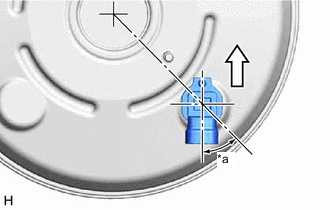
*a 45° +/- 20° 
Up Install the vacuum sensor assembly to the brake booster assembly as shown in the illustration.
-
-
INSTALL VACUUM WARNING SWITCH ASSEMBLY (for 8AR-FTS w/o Stop and Start System)
-
Install a new check valve grommet to the brake booster assembly.
-
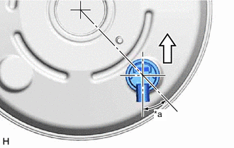
*a 45° +/- 20° Up Install the vacuum warning switch assembly to the brake booster assembly as shown in the illustration.
-
-
INSTALL BRAKE VACUUM CHECK VALVE ASSEMBLY
-
Install a new check valve grommet to the brake booster assembly.
-
Install the brake vacuum check valve assembly to the brake booster assembly.
-
-
INSTALL BRAKE MASTER CYLINDER PUSH ROD CLEVIS
-
Temporarily install the clevis lock nut and brake master cylinder push rod clevis to the brake booster assembly.
Note
Fully tighten the clevis lock nut when adjusting the brake pedal height.
-
-
INSTALL BRAKE BOOSTER GASKET
-
Install a new brake booster gasket to the brake booster assembly.
-
-
INSTALL BRAKE BOOSTER ASSEMBLY
-
Install the brake booster assembly to the vehicle body with the 4 nuts.
- Torque:
- 12.7 N*m { 130 kgf*cm, 9 ft.*lbf }
Note
Do not kink or damage the brake lines.
-
for 8AR-FTS w/ Stop and Start System:
-
Connect the connector to the vacuum sensor assembly.
-
-
for 8AR-FTS w/o Stop and Start System:
-
Connect the connector to the vacuum warning switch assembly.
-
-
-
INSTALL FRONT NO. 1 BRAKE TUBE
-
Engage the clamp to install the front No. 1 brake tube.
-
-
INSTALL REAR NO. 1 BRAKE TUBE
-
Engage the clamp to install the rear No. 1 brake tube.
-
-
CONNECT UNION TO CHECK VALVE HOSE
-
Connect the union to check valve hose to the brake booster assembly, and slide the clip to secure it.
-
-
INSTALL PUSH ROD PIN
-
INSTALL BRAKE PEDAL RETURN SPRING
-
Install the brake pedal return spring to the push rod pin and steering column assembly.
-
-
INSTALL BRAKE ACTUATOR WITH BRACKET
-
INSTALL FRONT NO. 2 BRAKE TUBE
-
INSTALL BRAKE MASTER CYLINDER O-RING
-
INSTALL BRAKE MASTER CYLINDER SUB-ASSEMBLY
-
INSTALL LOWER NO. 1 INSTRUMENT PANEL AIRBAG ASSEMBLY
-
BLEED BRAKE SYSTEM
-
INSTALL FRONT WHEEL RH
- Torque:
- 103 N*m { 1050 kgf*cm, 76 ft.*lbf }
-
INSPECT AND ADJUST BRAKE PEDAL