AUTOMATIC TRANSMISSION SYSTEM(for 8AR-FTS), Diagnostic DTC:P08CC7F
| DTC Code | DTC Name |
|---|---|
| P08CC7F | Shift Solenoid "J" Control Actuator Stuck Off |
DESCRIPTION
Based on signals from the transmission revolution sensors (NT, NC3 and SP2), the actual gear is detected.
If the detected gear is different than the commanded gear, the ECM detects related mechanical problems in the shift solenoid valves, transmission valve body assembly and automatic transmission assembly (clutch, brake, gear, etc.).
Tech Tips
| ECM commanded gear | 1st | 2nd | 3rd | 4th | 5th | 6th | 7th | 8th |
|---|---|---|---|---|---|---|---|---|
| Actual gear during SC2 stuck OFF malfunction | 1st | 2nd | 3rd | 4th | 5th | 6th (5th)*1 |
7th (5th)*2 |
8th (5th)*3 |
*1: Accelerator pedal position is 40% or more
*2: Accelerator pedal position is 50% or more
*3: Accelerator pedal position is 80% or more
| DTC No. | Detection Item | DTC Detection Condition | Trouble Area | MIL | Memory | Note |
|---|---|---|---|---|---|---|
| P08CC7F | Shift Solenoid "J" Control Actuator Stuck Off | 1. Diagnosis Condition, 2. Malfunction Status, 3. Malfunction Time, 4. Other
|
|
Comes on | DTC stored | SAE Code: P08CD |
MONITOR DESCRIPTION
The ECM commands gear shifts by turning the shift solenoid valves on and off. According to the input shaft revolution (speed), intermediate (counter) shaft revolution (speed) and output shaft revolution (speed), the ECM detects the actual gear (1st, 2nd, 3rd, 4th, 5th, 6th, 7th or 8th gear position). When the gear commanded by the ECM and the actual gear are not the same, the ECM illuminates the MIL and stores a DTC.
CAUTION / NOTICE / HINT
Note
Perform registration and/or initialization when parts related to the automatic transmission are replaced.
PROCEDURE
-
CHECK DTC OUTPUT (IN ADDITION TO DTC P08CC7E)
-
Connect the GTS to the DLC3.
-
Turn the engine switch on (IG).
-
Turn the GTS on.
-
Enter the following menus: Powertrain / Transmission / Trouble Codes.
Powertrain > ECT > Trouble Codes -
Read the DTCs using the GTS.
Result Result Proceed to DTC P08CC7F and DTC P07457F, P076A7E, P076A7F, P07757F, P07957F, P08CC7E, P28077F and/or P28167F are output A Only DTC P08CC7F is output DTCs other than P07457F, P076A7E, P076A7F, P07757F, P07957F, P08CC7E, P08CC7F, P28077F and P28167F are also output B Tech Tips
If any DTCs other than P07457F, P076A7E, P076A7F, P07757F, P07957F, P08CC7E, P08CC7F, P28077F and P28167F are output, perform troubleshooting for those DTCs first.
B 
GO TO DTC CHART Click here
A 
-
-
INSPECT SOLENOID (SC1) AND (SC2) VALVE
-
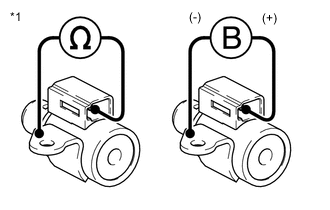
*1 Solenoid (SC1) and (SC2) Valves Remove the solenoid (SC1) and (SC2) valves.
-
Measure the resistance according to the value(s) in the table below.
Standard Resistance Tester Connection Condition Specified Condition Terminal of solenoid (SC1) valve connector - Solenoid (SC1) valve body 20°C (68°F) 11 to 15 Ω Terminal of solenoid (SC2) valve connector - Solenoid (SC2) valve body 20°C (68°F) 11 to 15 Ω -
Connect a positive (+) lead from the battery to the terminal of the solenoid valve connector, and a negative (-) lead to the solenoid body. Check that the valve moves and makes an operating sound.
OK Valve moves and makes an operating sound. Result Proceed to OK NG
NG
REPLACE SOLENOID (SC1) OR (SC2) VALVE Click here
OK
-
-
INSPECT SOLENOID (SL1), (SL2), (SL3), (SL4) AND (SL5) VALVE
-
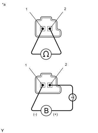
*a Component without harness connected
(solenoid (SL1), (SL2), (SL3), (SL4) and (SL5) Valves)
Remove the solenoid (SL1), (SL2), (SL3), (SL4) and (SL5) valves.
-
Measure the resistance according to the value(s) in the table below.
Standard Resistance Tester Connection Condition Specified Condition Terminal 1 of the solenoid (SL1) valve - terminal 2 20°C (68°F) 5.0 to 5.6 Ω Terminal 1 of the solenoid (SL2) valve - terminal 2 20°C (68°F) 5.0 to 5.6 Ω Terminal 1 of the solenoid (SL3) valve - terminal 2 20°C (68°F) 5.0 to 5.6 Ω Terminal 1 of the solenoid (SL4) valve - terminal 2 20°C (68°F) 5.0 to 5.6 Ω Terminal 1 of the solenoid (SL5) valve - terminal 2 20°C (68°F) 5.0 to 5.6 Ω -
Connect a positive (+) lead from the battery with a 21 W bulb to terminal 2 and a negative (-) lead to terminal 1 of the solenoid valve connector. Check that the valve moves and makes an operating sound.
OK Valve moves and makes an operating sound. Result Proceed to OK NG
NG
REPLACE SOLENOID (SL1), (SL2), (SL3), (SL4) OR (SL5) VALVE Click here
OK
-
-
INSPECT TRANSMISSION VALVE BODY ASSEMBLY
-
Check the transmission valve body assembly.
OK There is no foreign matter on each valve and they operate smoothly. Result Proceed to OK NG
NG
REPAIR OR REPLACE TRANSMISSION VALVE BODY ASSEMBLY Click here
OK
-
-
INSPECT TORQUE CONVERTER ASSEMBLY
-
Check the torque converter assembly.
OK The torque converter clutch operates normally. Result Proceed to OK NG
NG
REPLACE TORQUE CONVERTER ASSEMBLY Click here
OK
-
-
REPAIR OR REPLACE AUTOMATIC TRANSMISSION ASSEMBLY
-
Repair or replace the automatic transmission assembly.
Result Proceed to NEXT
NEXT
PERFORM A/T CODE REGISTRATION Click here
-