AUTOMATIC TRANSMISSION SYSTEM(for 8AR-FTS), Diagnostic DTC:P076A11
| DTC Code | DTC Name |
|---|---|
| P076A11 | Shift Solenoid "H" Control Circuit Short to Ground |
DESCRIPTION
Based on the ON-OFF combinations of the solenoid (SL1, SL2, SL3, SL4, SL5, SC1 and SC2) valves, the ECM performs gear shifts from 1st gear to 8th gear.
If a circuit related to a solenoid valve is open or shorted, the ECM uses the fail-safe function to turn other solenoid valves on or off. If all solenoid valves are malfunctioning, only the mechanical fluid pressure circuit will function and some manual operation will be possible. If an open or short has occurred, the ECM cuts power to the malfunctioning solenoid valve.
| DTC No. | Detection Item | DTC Detection Condition | Trouble Area | MIL | Memory | Note |
|---|---|---|---|---|---|---|
| P076A11 | Shift Solenoid "H" Control Circuit Short to Ground | 1. Diagnosis Condition 2. Malfunction Status 3. Malfunction Time 4. Other
|
|
Comes on | DTC stored | SAE Code: P099E |
MONITOR DESCRIPTION
This DTC indicates a short in the solenoid (SC1) valve circuit. When there is an open or short in any shift solenoid valve circuit, the ECM detects the problem, illuminates the MIL and stores a DTC.
When the solenoid (SC1) valve is on, if its resistance is 8 Ω or less, the ECM determines there is a short in the solenoid (SC1) valve circuit.
WIRING DIAGRAM
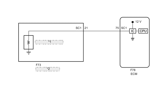
| *1 | Solenoid (SC1) Valve |
| *2 | Transmission Wire |
CAUTION / NOTICE / HINT
Note
Perform registration and/or initialization when parts related to the automatic transmission are replaced.
Tech Tips
After performing repair, clear the DTCs and perform the following procedure to check that DTCs are not output.
-
While the vehicle is being driven, move the shift lever to M, select the M1 (1st gear) range and perform an engine brake.
-
Check for DTCs again.
PROCEDURE
-
CHECK HARNESS AND CONNECTOR (TRANSMISSION WIRE (SOLENOID (SC1) VALVE) - ECM)
-
Disconnect the F78 ECM connector.
-
Measure the resistance according to the value(s) in the table below.
Standard Resistance Tester Connection Condition Specified Condition F78-75 (SC1) - Body ground 20°C (68°F) 11 to 15 Ω Result Proceed to OK NG
NG 
CHECK HARNESS AND CONNECTOR (TRANSMISSION WIRE - ECM) Click here
OK 
-
-
REPLACE ECM
-
Replace the ECM.
Result Proceed to NEXT
NEXT 
PERFORM A/T CODE REGISTRATION Click here
-
-
CHECK HARNESS AND CONNECTOR (TRANSMISSION WIRE - ECM)
-
Disconnect the F73 transmission wire connector.
-
Disconnect the F78 ECM connector.
-
Measure the resistance according to the value(s) in the table below.
Standard Resistance Tester Connection Condition Specified Condition F73-21 (SC1) or F78-75 (SC1) - Body ground and other terminals Always 10 kΩ or higher Result Proceed to OK NG
NG
REPAIR OR REPLACE HARNESS OR CONNECTOR (TRANSMISSION WIRE - ECM)
OK
-
-
INSPECT SOLENOID (SC1) VALVE
-
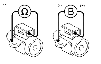
*1 Solenoid (SC1) Valve Remove the solenoid (SC1) valve.
-
Measure the resistance according to the value(s) in the table below.
Standard Resistance Tester Connection Condition Specified Condition Terminal of solenoid (SC1) valve connector - Solenoid (SC1) valve body 20°C (68°F) 11 to 15 Ω -
Connect a positive (+) lead from the battery to the terminal of the solenoid valve connector, and a negative (-) lead to the solenoid body. Check that the valve moves and makes an operating sound.
OK Valve moves and makes an operating sound. Result Proceed to OK NG
OK
REPAIR OR REPLACE TRANSMISSION WIRE Click here
NG
REPLACE SOLENOID (SC1) VALVE Click here
-